F3D
Adapter gắn rack cho switch TP-Link TL-SG116… 1

1 image

Dụng Cụ Tiện Ích

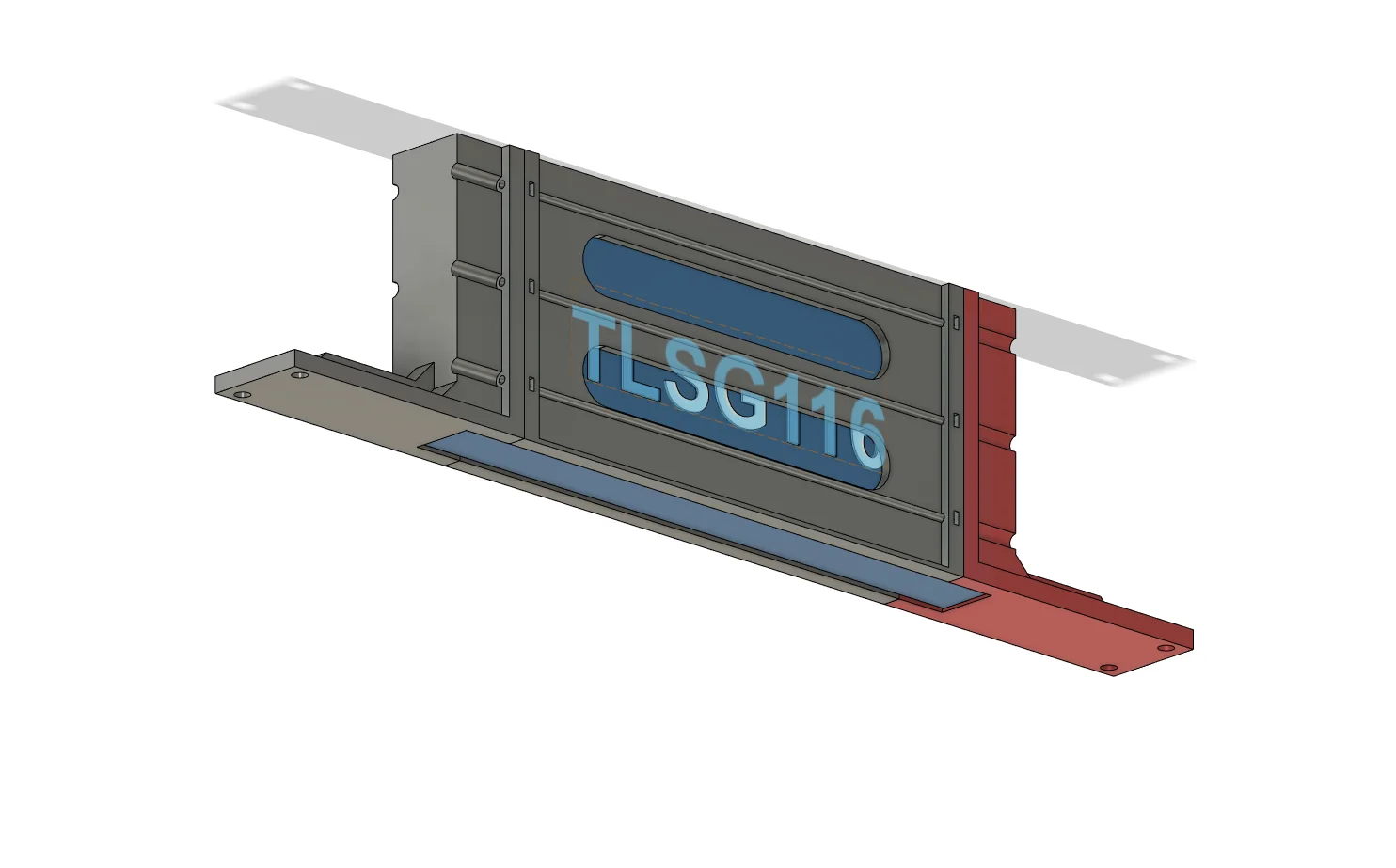
Adapter gắn rack cho switch TP-Link TL-SG116 (Rackmount Adapter)

Remix of Adapter gắn rack cho Netgear GS116 Switch (Rackmount Adapter) By Chriswak

By Chriswak

Downloads
366
Likes
24
Views
2,890
Remixes
1

Files 3 666.3 KB

  • TLSG116-Bracket_1777710845.stlSTL · 143.2 KB
  • TLSG116-Coupler-Cutouts_1777710845.stlSTL · 275.8 KB
  • TLSG116-Coupler-Solid_1777710847.stlSTL · 247.3 KB

Make a variant with AI

Build another version of this model.

Open Studio

Remix versions 1

See all 1 remix

Description

1. Non-printed Parts Required

  • (4) Server rack Cage nuts
  • (4) M6 x 14mm (or longer) screws for rack mounting
  • (12) M3 nuts, for switch Coupler plates
    • You can get away with only (8) if you don't need it very secure.
  • (12) M3 x 16mm (or longer) screws, for switch Coupler plates
    • You can get away with only (8) if you don't need it very secure.
  • M3 Driver (slimmer is better)

2. Printed Parts

  • (2) TLSG116-Bracket, one for left side and one for right side
  • (2) TLSG116-Coupler, one for top and one for bottom
    • Two coupler types are available; one solid and one with cutouts to help save plastic. You can choose any combination as long as you end up with two coupler plates.

3. Adapter Assembly

  1. Each Coupler plate has outward-facing rectangular slots that securely hold the M3 Nuts. Press-fit your M3 Nuts into the slots of each Coupler plate - some force will be necessary!
    If you want it very secure, fill all 6 slots in each of the Coupler plates (total of 12 nuts required). If you don't need it very secure, simply fill 4 corner slots in each of the Coupler plates (total of 8 nuts required). I used only 8. Set the plates aside for now.
  2. Each Bracket has a flat overhang feature on the front side and small rounded features in each rear corner. Choose a starting side and firmly push the Switch into one of the Brackets, ensuring that the Bracket's flat overhang feature is on the front side of the Switch and the Bracket's rounded corner features are at the rear of the Switch.
  3. Firmly attach the remaining Bracket to the opposite side of the switch, ensuring that the Bracket's flat overhang feature is on the front side of the Switch and the Bracket's rounded corner features are at the rear of the Switch.
  4. Set one of the Coupler plates between the Brackets, ensuring that the M3 Nut Slots are facing away from the Switch and that the flat edge of the Coupler plate faces the front of the Switch. The M3 Nut Slots will be aligned with the Bracket's M3 screw holes when you've got the correct orientation.
  5. After ensuring alignment between the Coupler plate's M3 Nut Slots and the Bracket's M3 screw holes, drive the M3 x 16mm screws through the Bracket and into the Coupler plate.
  6. Carefully flip over the assembly and set the remaining Coupler plate between the Brackets, ensuring correct orientation. Drive the remaining M3 x 16mm screws through the Bracket and into the Coupler plate.
  7. Using your Cage nuts and M6 screws, mount the assembly into your rack and enjoy the saved space :)

Read more Show less

Print spec

Formats
stl
Model files
3
Total size
666.3 KB
Largest file
275.8 KB

0 comments

See all