

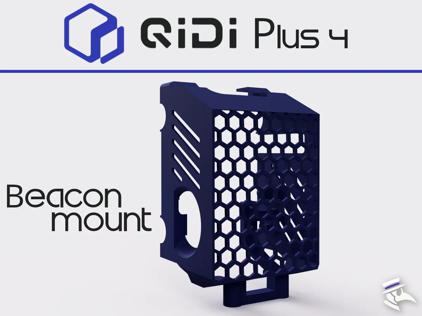


Kẹp giữ sợi Filament
 Bytinx_1344834Likes1.2KDownloads6K
Remix of Giá đỡ Beacon3D cho Qidi Plus4 By stew675_2525901
Build another version of this model.
⚠ Important Please Read ⚠
Print and use this Qidi Plus 4 Beacon Mount at your own risk. I assume no liability for any damage, injury, or malfunction arising from its use, misuse, or from the characteristics of the material you choose to print it with.
My goal with this project is simple and straightforward: To improve the overall looks of the beacon mount, and secondly make it more accessible to the non enthusiasts. With that being stated, none of this would be possible without Stew675 and his amazing Beacon mount. You can follow my guide or his, they both have the same result, but you get a little more hands on with his guide. Either way...Let's go...
All links are non-affiliate
Avoid low temperature filaments.
Choose Glass or Carbon Fiber filaments for greater rigidity
PC, PA, PPA (aka PAHT), or PET with CF or GF filling are usually all good choices
Use PC, or PPA if you print with high temperature filaments on a regular basis, as the bed temperatures may cause some deformation over time
Print the Beacon Mount face down as already orientated. Use auto organic trees on the build plate only. Supports come off easy, but be careful with the supports on the crossmember. Take your time and snip the base off that tree before trying to remove. Use 999 walls.
Nozzle: .4
Filament: PA | PC | PPA (See Above)
Walls: 999 (⚠Important⚠)
Layer Height: .2
Supports: Yes, Auto organic tree supports on the build plate only
Bed Adhesion: Yes; Brim
Power Loss Recovery does not work correctly yet when using the Beacon probe. A solution is being worked on for this, but for now do not expect to be able to safely resume prints after a power loss event
The original guide can be found here: Stew's Beacon Guide
Relax, You have got this
First we are going to Install the Beacon software onto your Qidi Plus 4. To do this we need a PC or Mac that is connected to the same network that the machine is and we will also need the printers IP address(from the printer itself). We need to open a command prompt or terminal. Once open, type: ssh [email protected] replacing the X's with your IP address. You will then be prompted for a password. It is "makerbase". The cursor won't move just hit enter after typing it. You will be greeted by this screen:
You are officially in your machine and ready to give it three separate commands, pressing enter after each individual one.
cd /home/mks
git clone https://github.com/beacon3d/beacon_klipper.git
./beacon_klipper/install.sh
First thing to do is to install the two magnets. We will need a dab of super glue for this. You will need to pay attention to polarity on the side with the crossmember as there is an embedded magnet in the toolhead we are attaching to. The other side doesn't matter as it magnetizes to a screw. A bit of glue and a firm press.
We need to remove the front cover of your toolhead in your printer by lifting up, then off. On the right hand side you have a probe that we will no longer need. Remove the 2 screws, unplug the probe and remove it. We will need those two screws to mount the Toolhead cover. Take them and start threading them in to the crossmember in the same hole each came out of(long on top) just enough to hold them in until we can tighten them down. See image below on right.
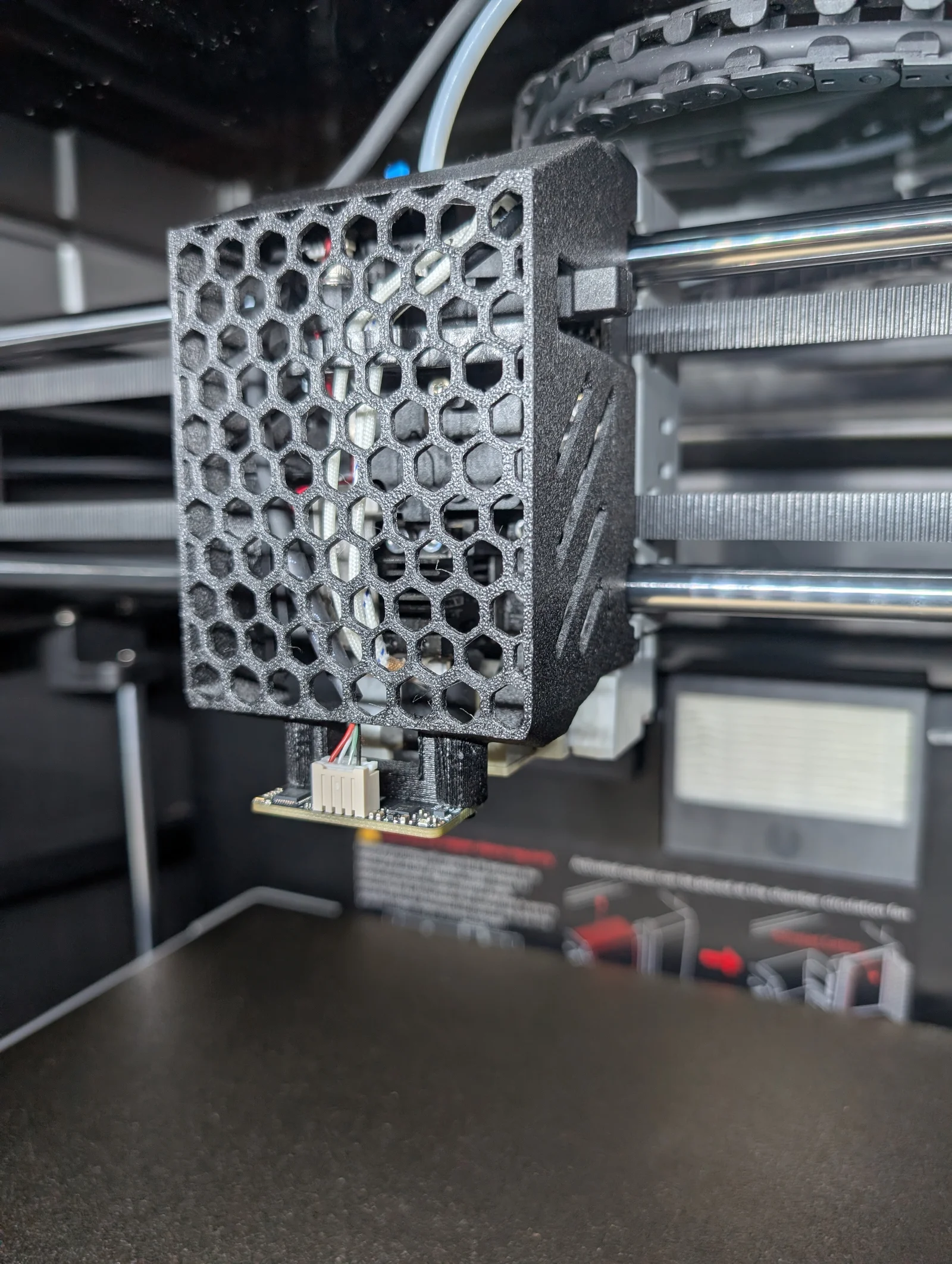
Your beacon came with a few screws. We will be using the shorter ones. We want to attach the Beacon to the mount with the connector facing up and on the outside of the cover. top left pic. Careful to not overtighten and strip them.
Next we want to get the screws started into the crossmember through the front honeycomb. Image above on right. This will make it much easier to tighten down once the cover is on. Make sure you used the right screw in the right spot. Longer on top. Screws should thread in without issue.
Time to plug the Beacon in to the board. You are going to run the cord through the inside of the cover and out to the beacon probe. It's a tight fit and you may struggle for a minute but you will get it plugged in. Mount the toolhead and everything should hold in place. Tighten the screws going through the honeycomb all the way until you feel resistance, careful not to strip them.
The USB cord can be ran and zip tied to the drag chain, going through the wire access hole. Your goal is to plug it into one of the bottom two USB ports on the left hand side of the motherboard. I recommend unplugging the third one down and using it as it will just get rid of the USB port on the top back of the printer. If you run offline or ethernet you can pull out the WiFi dongle and use the forth spot.
We will need to access the printer via a computer again. Same process: ssh [email protected] password: 'makerbase'. We have two lines to run here. The first one will give you your serial number. Write down your serial number., you will need it.
ls /dev/serial/by-id/usb-Beacon* your serial is after "RevH_". See below
wget -O /home/mks/klipper/klippy/extras/probe.py https://raw.githubusercontent.com/qidi-community/Plus4-Wiki/refs/heads/main/content/bed-scanning-probes/Beacon3D/RevH-Normal/probe.py
Turn off printer at the printer power switch. Wait 20 seconds. Turn back on.
The rest will be handled in your Slicer. Click device at the top after opening.
More specifically the configuration tab under the device tab. Circled in green on the left in the image above. We are replacing the 3 files circled in blue, using the toolbar circled in pink in the image above.
Printer.cfg, gcode_macros.cfg and Kamp_Settings.cfg. Check the box next to them and then click the trash can on the toolbar circled in pink in the image above to delete the current files. Now on that same bar click the "+" and select "upload files". You want to select the mod files you just downloaded and unzipped of the same name. After replacing the 3 files you removed you are ready to proceed.
Double click to open the printer.cfg file. Scroll all the way to the bottom, and find the Beacon section pictured below. On the serial line you will need to put your serial number in. Top line far right. After RevH_ Circled in pink in the image below. Then click save.
Time to enable your new purge line. We will do this on the prepare tab of the slicer. Circled in red below you can edit your printer's settings. Click this, then click Machine G-Code and everything should look similar to below
In the Machine Start G-Code the stock Qidi purge line will look like below. We want to delete it and put "Line_Purge" in its place like circled in green above. Remember to click save, at the top; by the printer name.
G0 Z[initial_layer_print_height] F600
G1 E3 F1800
G1 X{(min(print_bed_max[0] - 12, first_layer_print_min[0] + 80))} E{85 * 0.5 * initial_layer_print_height * nozzle_diameter[0]} F3000
G1 Y{max((min(print_bed_max[1] - 3, first_layer_print_min[1] + 80) - 85), 0) + 2} E{2 * 0.5 * initial_layer_print_height * nozzle_diameter[0]} F3000
G1 X{max((min(print_bed_max[0] - 12, first_layer_print_min[0] + 80) - 85), 0)} E{85 * 0.5 * initial_layer_print_height * nozzle_diameter[0]} F3000
G1 Y{max((min(print_bed_max[1] - 3, first_layer_print_min[1] + 80) - 85), 0) + 85} E{83 * 0.5 * initial_layer_print_height * nozzle_diameter[0]} F3000
G1 X{max((min(print_bed_max[0] - 12, first_layer_print_min[0] + 80) - 85), 0) + 2} E{2 * 0.5 * initial_layer_print_height * nozzle_diameter[0]} F3000
G1 Y{max((min(print_bed_max[1] - 3, first_layer_print_min[1] + 80) - 85), 0) + 3} E{82 * 0.5 * initial_layer_print_height * nozzle_diameter[0]} F3000
G1 X{max((min(print_bed_max[0] - 12, first_layer_print_min[0] + 80) - 85), 0) + 3} Z0
G1 X{max((min(print_bed_max[0] - 12, first_layer_print_min[0] + 80) - 85), 0) + 6}
Do a firmware restart. Now just a final calibration will get you going. Click the device tab and Copy and Paste these lines into your console , hit enter and just wait for it to finish.
G32
G28 X Y
G1 X150 Y150
BEACON_AUTO_CALIBRATE
G29
G31
SAVE_CONFIG
You are all finished now, Enjoy!
Tramming the bed has changed with your new Beacon probe. Gone are the old ways of using a piece of paper. The Beacon Probe knows precisely how far away the nozzle is from the bed. This makes the task of tramming the bed using the four nuts under the print bed a lot easier.
To use this new tramming method, first home all axis, afterwards pre-heat your print bed to a temperature you often print at and let it heat soak for five minutes. Then call SCREW_ADJUST_START from the device tab console window. Finally call SFL, SFR, SBL, or SBR, depending on which corner you want to start with. You will need to do all four independently. You will be greeted with a z-offset number that will look like z=x.xxxx. The goal is to get within +/- 0.02mm of Z=2.00, although this will not be perfectly obtainable. After adjusting the bed screw, call the corner again to get the new z-offset. Repeat for the three remaining corners.
Stew's guide is the best possible thing. Scroll all the way to the bottom for his troubleshooting section. I am obviously around so if you do have a question just message me.
Or take a look at any of my other Plus 4 Mods
❤ a few of my models
and
Bytinx_1344834Likes1.2KDownloads6K

 Byprusa-researchLikes0Downloads777

 Byarhi_585078Likes64Downloads540

 ByHanzo3dLikes155Downloads413

 ByGeek5DLikes147Downloads484

 ByBrokentooth_designsLikes23Downloads407

 By3DSourcererLikes48Downloads377

 ByWyomingWolf_261196Likes52Downloads428

 Byartme-3dLikes0Downloads332

 Bytopronix_2170418Likes41Downloads296

 Bybloblis67Likes0Downloads316

 ByAnthonyDouri_1604724Likes24Downloads220