



CORE One/+ INDX printed parts
 Byprusa-researchLikes0Downloads2.7K
Build another version of this model.
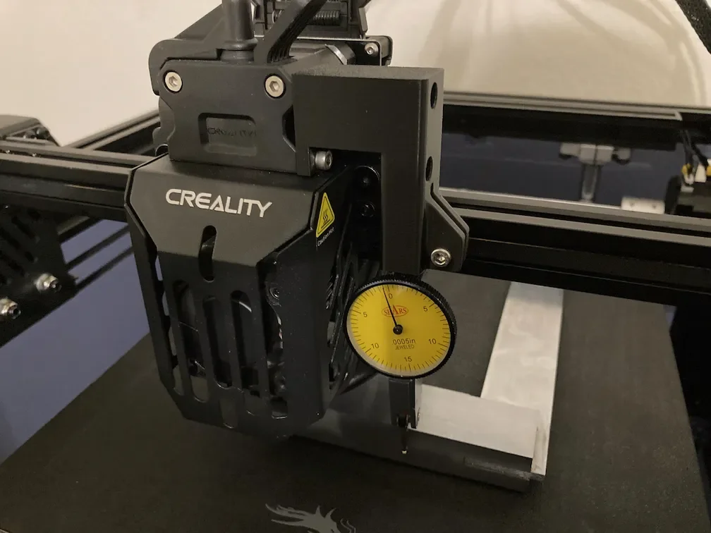
This is a bracket for the dial test indicator that screws to the right side of the standard extruder of Ender-5 S1 printer.
It allows to run the test indicator against a known square block (1-2-3 block, machinist square, etc) to check that X/Y axes are perpendicular.
The bracket mounts with two M3x6 screws. To clamp the indicator, I used M3x10 screw and M3*H3 threaded insert.
Printing should not require any supports or any special settings. Print top side down.
I used the following alignment process. All motors were disengaged at this point, and I moved the gantry by hands.
Probably, would not hurt to check that the frame is square. However, if both sides of the frame are parallel to each other, this process would make the gantry to be perpendicular to them even if the frame itself is skewed.
The might be some other considerations as to in which order to adjust everything (the wheels, the belts, the coupler). I don't have experience aligning 3D printers, I only adjusted the coupler.
It is possible to run the gantry under the power, but make sure to install the bracket AFTER homing the motors. The bracket interferes with X axis homing and you can damage your printer if you home with the bracket installed.
After doing the alignment, I re-checked it by running some G-code to move the extruder. Moving by hand during the alignment process might move gantry slightly differently when running under the power, so probably a good idea to check with the motors running at the very end.
NOTE: Once again, the bracket interferes with X axis homing!
Byprusa-researchLikes0Downloads2.7K

 Bytinx_1344834Likes1.2KDownloads6K

 BydarienLikes0Downloads1K

 Byla-cave-au-chatLikes0Downloads967

 ByvertigomakesLikes0Downloads563

 By3DPrintDemonLikes0Downloads328

 Bypeter-van-der-waalLikes0Downloads255

 Bychris-hillLikes0Downloads261

 ByhumebeamLikes0Downloads128


 BykingnothingLikes0Downloads181

 Byrobert-samplesLikes0Downloads187