

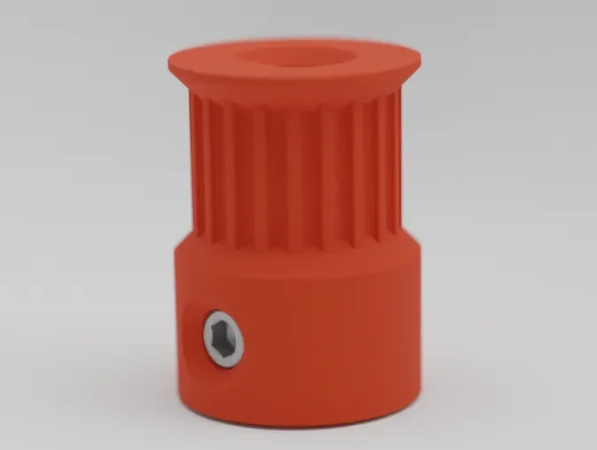



CORE One/+ INDX printed parts
 Byprusa-researchLikes0Downloads2.7K
Build another version of this model.
There are already working implementation of 'gt2 pulleys' available. Nonetheless that implementations are mostly based on SCAD which results in mesh files. If you prefer to model project parts directly in Fusion 360, this thing is for you!
Regardless of the theoretical foundation of this design it should work fine for all your gt2 pulley needs.
You can change the design via Fusion's User Parameters feature. But be careful when increasing the grooves count. For some reason Fusion struggles with large changes like 20 to 80 but works fine with 20 to 50 to 80.
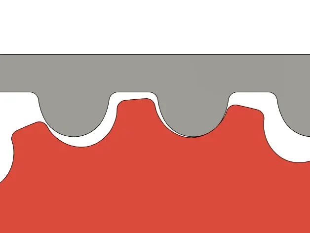
It took me quite some time to get my head around the math behind the grooves. Contrary to popular belief the profile is not just an inverse of the belts teeth. For a belt wrapped all around a pulley it would be that way, but given that a belt leaves the pulley at some point there appears an issue. The reason being, that the belt and pulley move exactly the same distance, the belt in a straight line - to or away from the wheel - and the pulley in a circular path around it's center. The grooves profile has to account for the change in distance and orientation to the belt. The mathematical concept to describe this relative change is called 'involute'. Have a look at the attached Fusion 360 file to get an idea how it works.
If you have doubts about this tooth profile I would love to discuss them in the comments. (e.g. contact surface vs. clearance)
The critical part of these pulleys is the teeth geometry which fortunately is printable with a standard 0.4 mm nozzle. The overhangs are the overhangs are designed to be 50 deg, so up to 0.3 mm layer height shouldn't be a problem.
The provided files are more or less just meant to be examples nonetheless here you'll find their relevant dimensions
Part Name
Bore Hole Diameter
Pitch Circle Diameter
20T-5mm-dshaft-grub-screw
5.5 mm
12.732 mm
20T-5mm-dshaft-pressfit
5.3 mm
12.732 mm
40T-5mm-dshaft-pressfit
5.3 mm
25.465 mm
60T-5mm-dshaft-pressfit
5.3 mm
38.197 mm
If you have problems with the roundness of these prints, consider mechanical or software-side 'skew correction'
Byprusa-researchLikes0Downloads2.7K

 Bytinx_1344834Likes1.2KDownloads6K

 BydarienLikes0Downloads1K

 Byla-cave-au-chatLikes0Downloads967

 ByvertigomakesLikes0Downloads563

 By3DPrintDemonLikes0Downloads328

 Bychris-hillLikes0Downloads263

 Bypeter-van-der-waalLikes0Downloads256

 ByhumebeamLikes0Downloads128


 BykingnothingLikes0Downloads181

 Byrobert-samplesLikes0Downloads187