



Còi Tàu Hơi Nước Mini
 ByfifindrLikes500Downloads4K
Build another version of this model.
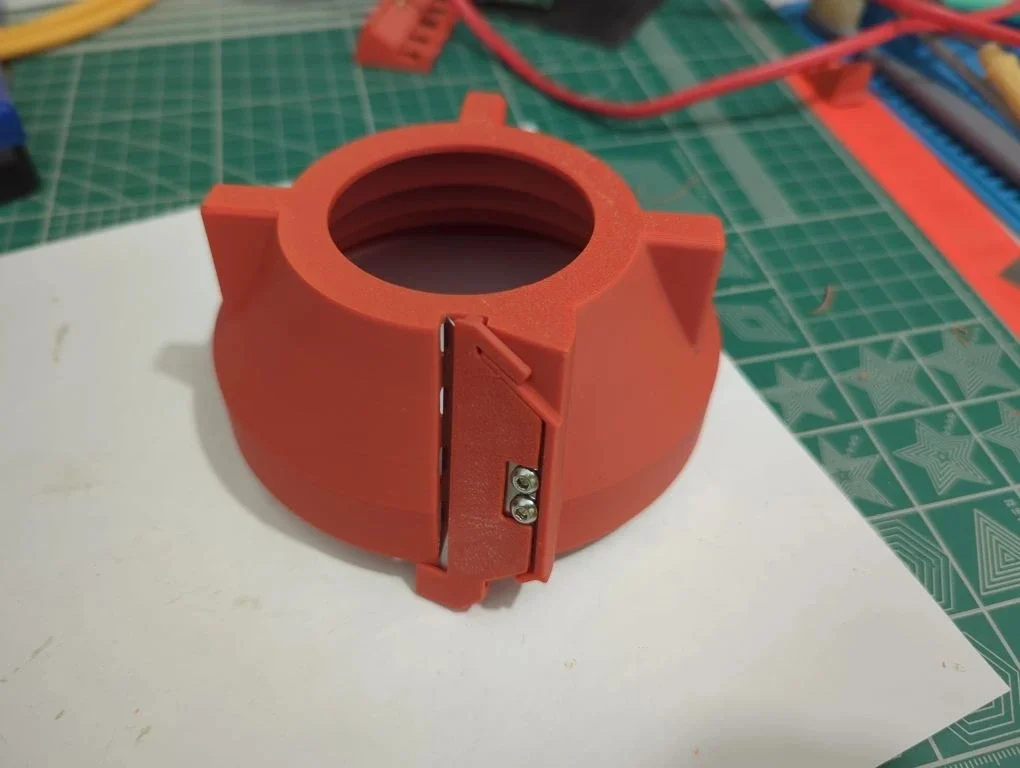
# 15° PVC-U Pipe Chamfer Tool (Multi-Diameter 110, 90, 75, 63 mm)
Use hot water to soften the plastic!
A compact, multi-diameter manual pipe beveling tool (chamfering "cup") specifically designed for preparing metric **PVC-U** pipes before solvent welding (glueing).
To ensure a reliable leak-proof connection, standards like **ISO 1452** and **DVS 2204-1** strictly require a **15-degree chamfer** angle. This angle acts as a wedge, smoothly distributing the cement inside the fitting socket instead of scraping it off (which happens with a 45° or 90° cut).
Thanks to the stepped offset cone design, a single utility blade covers all 4 pipe sizes perfectly at the exact required 15° angle!
---
### 🔄 Update Log / Changelog
#### v1.2 — Reduced the amount of plastic required for printing
#### v1.1 — Fitment & Safety Update
* Fixed Pipe Fitment (Tolerances): Increased internal cylinder clearances for all diameters (110, 90, 75, 63 mm) to comply with ISO 1452-2 real-world pipe tolerances and compensate for 3D printer plastic shrinkage. Pipes now slide in smoothly without binding. (I hope)
* Added Blade Guard (Safety Feature)
* Optimized Transitions: Tweaked the internal lead-in chamfers for even easier pipe centering.
---
#### v1.0 — Initial Release
* First prototype design with a stepped offset cone and M3 heat-set inserts.
---
### 🛠 Bill of Materials (BOM)
To assemble this tool, you will need the following hardware:
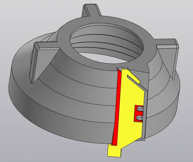
* **Blade:** 1x Standard Trapezoid Utility Blade (Stanley type, 62mm x 19mm)
* **Screws:** 2x M3x6mm Button Head (or Cap Head) Hex Screws
* **Threaded Inserts:** 2x M3 Brass Heat-Set Inserts (Outer Diameter: 4.5mm, Length: 4.0mm)
### 📐 3D Design Technical Details
* **Insert Pockets:** The holes for the heat-set inserts are pre-sized at **4.1 mm** in diameter to ensure a perfect plastic flow and tight fit when melting them in.
* **Ergonomics:** The outer shell features heavy gripping ribs for a comfortable manual twist. An integrated direction arrow shows the correct rotation path.
* **Blade Clamp:** Uses a simple 2-screw clamping plate that provides maximum rigidity to prevent blade flexing during tough cuts.
---
### 🖨 Recommended Print Settings
For maximum durability and structural integrity under twisting forces, please use the following slicing guidelines:
* **Material:** PETG, ASA, or ABS (PLA can be used for testing, but might be too brittle for heavy pipe friction)
* **Perimeters (Walls):** 4 or more (Crucial for strong blade mounts and heat-set inserts)
* **Top/Bottom Layers:** 5
* **Infill:** 30% - 40% (Gyroid or Grid for high torsional strength)
* **Supports:** No supports needed if oriented correctly (flat base down).
---
### 💡 Assembly & Usage Tips
1. Melt the two M3 brass inserts into the housing using a soldering iron. Ensure they sit flush or slightly sub-flush.
2. Insert the Stanley blade, place the clamping plate over it, and secure it with the M3x6mm screws. *Do not overtighten to avoid stripping the plastic or crushing the insert.*
3. Push the pipe into the corresponding stepped section and rotate **clockwise** while applying gentle pressure.
Feel free to post your makes, post comments, and share your experience if you use it on real PVC pipes!
ByfifindrLikes500Downloads4K

 Byquibeck_3353173Likes965Downloads1.9K

 ByleonicLikes0Downloads1.4K

 ByVC_DesignLikes679Downloads3.6K

 ByDan Schwartz SchwartzLikes744Downloads3.4K

 Bykjus_448782Likes314Downloads674

 ByelitailLikes0Downloads130

 Bychubbs8697_2027893Likes585Downloads1.7K

 Byvc-designLikes0Downloads3.2K

 BywurthLikes0Downloads190

 ByRungeKuttaLikes229Downloads1.2K

 ByJeremyVillalo_760366Likes68Downloads767