



DIY
Hộp bảo vệ module DS18B20 "Plugable Terminal" (ESP32)
- Downloads
- 1
- Likes
- 0
- Views
- 37
- Remixes
- 0
- Comments
- 0
Files 2 291 KB
- Body_DS18B20_1783587100.stlSTL · 284.8 KB
- Lid_DS18B20_1783587100.stlSTL · 6.1 KB
Make a variant with AI
Build another version of this model.
Details
- Model ID
- #409472
- Category
- DIY
- Published
Description
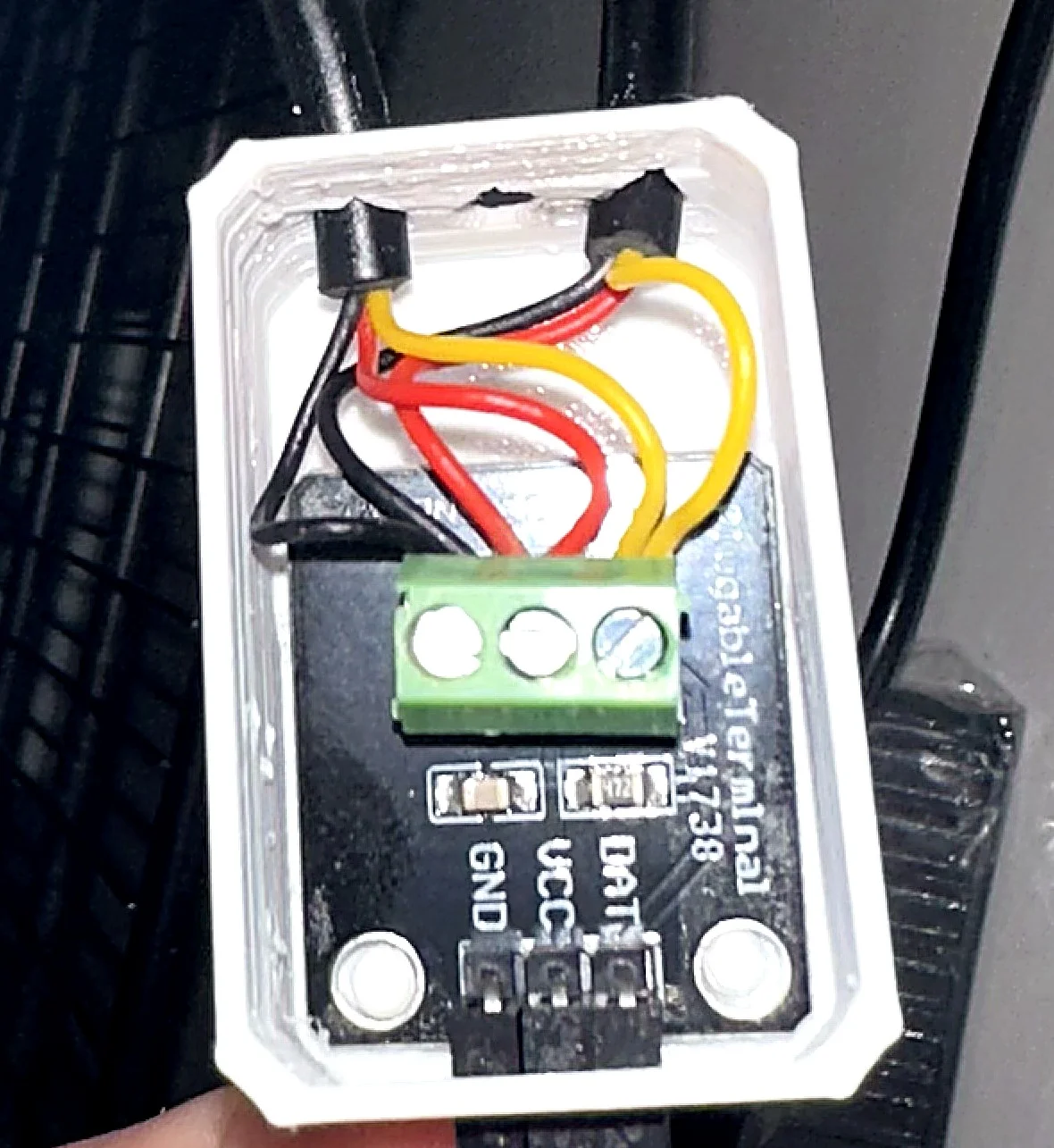
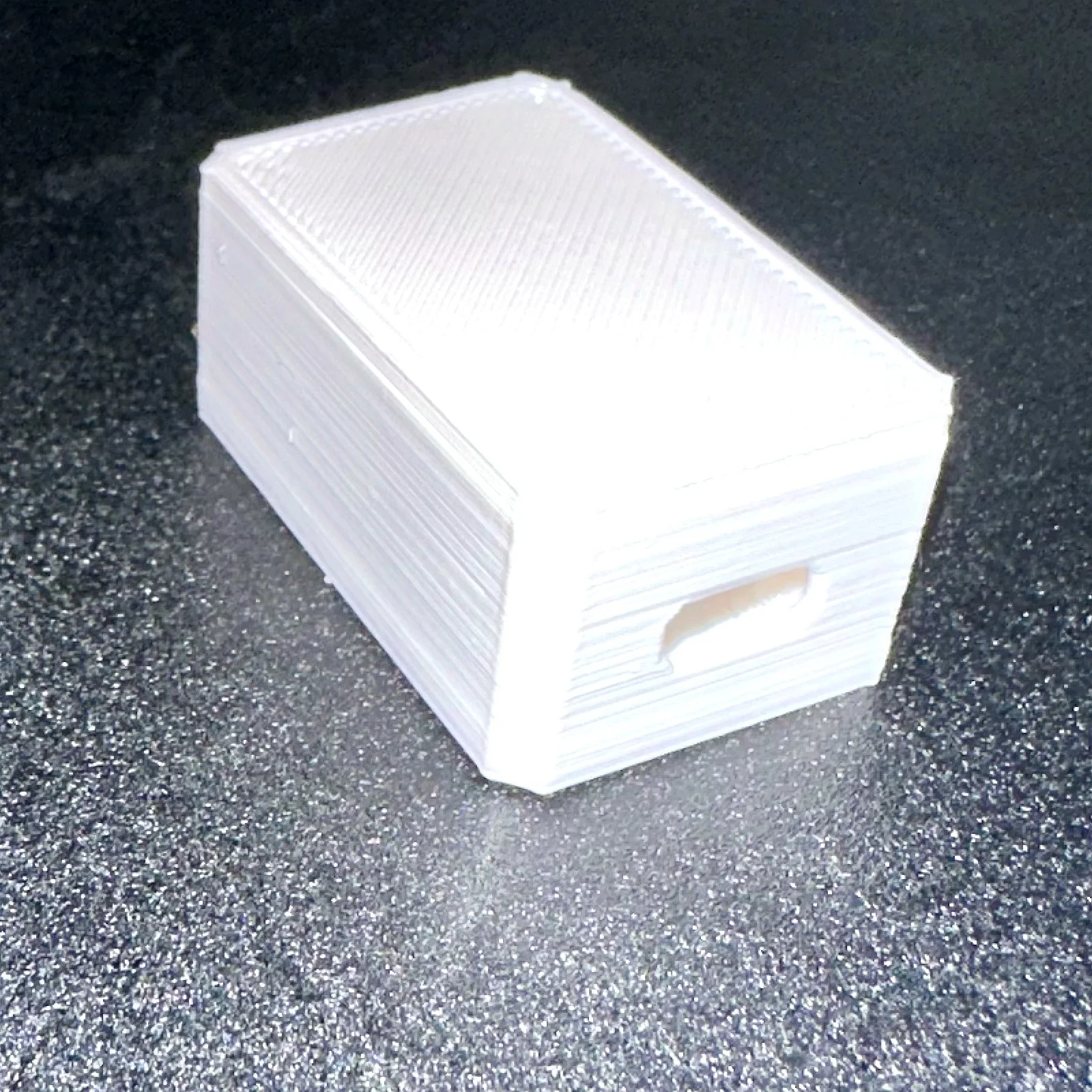
A compact two-part enclosure (base + lid) that protects the common **DS18B20 "Plugable Terminal" breakout board** — the one with the green screw terminal and the DAT / VCC / GND header (PCB marked V1738). I use it to wire a DS18B20 temperature sensor to an ESP32, but it fits any 3.3 V / 5 V MCU that talks to this board.
The box keeps the exposed PCB, screw terminal and jumper wires safe from dust, shorts and accidental knocks, while leaving the cabling accessible through the side openings.
Features
-
Snug fit around the standard DS18B20 plugable-terminal breakout.
-
Separate base + lid so you can service the wiring without desoldering anything.
-
Side cable pass-throughs for the sensor lead and the DAT/VCC/GND jumpers, shaped as teardrops so they print clean with no bridging and no supports.
-
The teardrop port is 4 mm — sized to grip the DS18B20 cable snugly with no play, acting as built-in strain relief so tugging the cable won't stress the PCB.
-
Chamfered edges — no sharp corners, cleaner print, easier to handle.
-
Small footprint, prints in minutes with almost no filament.
Dimensions
Part
Size (X × Y × Z)
Base
37 × 24 × 15.1 mm
Lid
37 × 24 × 2.5 mm
Assembled
37 × 24 × 17.5 mm
What you need (not included)
-
DS18B20 "Plugable Terminal" breakout board (screw-terminal version, DAT/VCC/GND).
-
DS18B20 temperature sensor (bare or waterproof probe).
-
Jumper wires + your MCU (ESP32, Arduino, etc.).
Files
-
Base –
Body_DS18B20.stl -
Lid –
Lid_DS18B20.stl
Print settings
Printed and tested on a Creality Ender-3 V2 Neo in PLA:
Setting | Value
Layer height
0.2 mm
Infill
15–20 %
Walls
3 perimeters
Supports
Not required
Adhesion
None (brim optional)
Nozzle
220 °C
Bed
60 °C
Orientation
Base printed open-side up, lid flat
No supports needed if you print the base with the open side facing up.
Assembly
-
Seat the breakout board inside the base.
-
Route the sensor lead and the DAT/VCC/GND wires through the side openings.
-
Press the lid on top.
Notes
-
Designed in FreeCAD. Source
.FCStdcan be shared on request if you want to remix or resize it. -
If your board is a slightly different variant, scale on the X/Y axes to adjust the internal clearance.
Feedback & improvements welcome
Got an idea to make this better — a tighter fit, extra mounting options, a different cable routing? Leave a comment or post a "Make". Suggestions and remixes are very welcome, and I'll fold good ones into future versions.
Prints, remixes and photos welcome — enjoy! 🌡
Print spec
- Formats
- stl
- Model files
- 2
- Total size
- 291 KB
- Largest file
- 284.8 KB
0 comments
You may also like 12 models
See all-
-
Bộ chuyển đổi từ khe Keyhole sang thanh ray DIN!
 ByBrokentooth_designsLikes83Downloads448
-
Chân Đế Loa Tùy Chỉnh (Customizable Speaker Stand)
 ByAdam Záhořák ZáhořákLikes39Downloads251
-
Ngăn Kéo Đa Năng Lắp Ghép Modular
 ByWilko_SLOLikes935Downloads2K
-
Mẫu gảy đàn Guitar (Guitar Pick) in 3D tùy chỉnh độ dày
 ByWolf_115355Likes513Downloads8.4K
-
Bộ sưu tập 11 nhân vật mô hình Mecca Chameleon in 3D vui nhộn
 ByZED4EverLikes313Downloads5.2K
-

Cable Mount - Kẹp Giữ Dây Cáp (Có Lỗ Bắt Vít)
 ByVC_DesignLikes271Downloads751
-
-
Còi Tàu Hơi Nước Mini
 ByfifindrLikes500Downloads4K
-
Hộp bảo vệ 3D cho Shelly 1 / 1PM Case - Gọn gàng và an toàn
 Bymrfixit_324954Likes65Downloads473
-
Dụng cụ mở hộp nhỏ gọn | Dao cắt thùng carton an toàn in 3D
 ByDan Schwartz SchwartzLikes744Downloads3.4K
-
SpoolGrid — Hệ thống ngăn kéo mô-đun tận dụng lõi nhựa Prusament
 Bydona3d_Likes456Downloads676


