



SolderMate - Fully 3D Printed Desk Soldering Companion
 ByleonicLikes0Downloads1.4K
Remix of DIY RC GoCart - TableRacer (Xe GoCart RC mini chạy trong nhà) By Paul_191420
Build another version of this model.
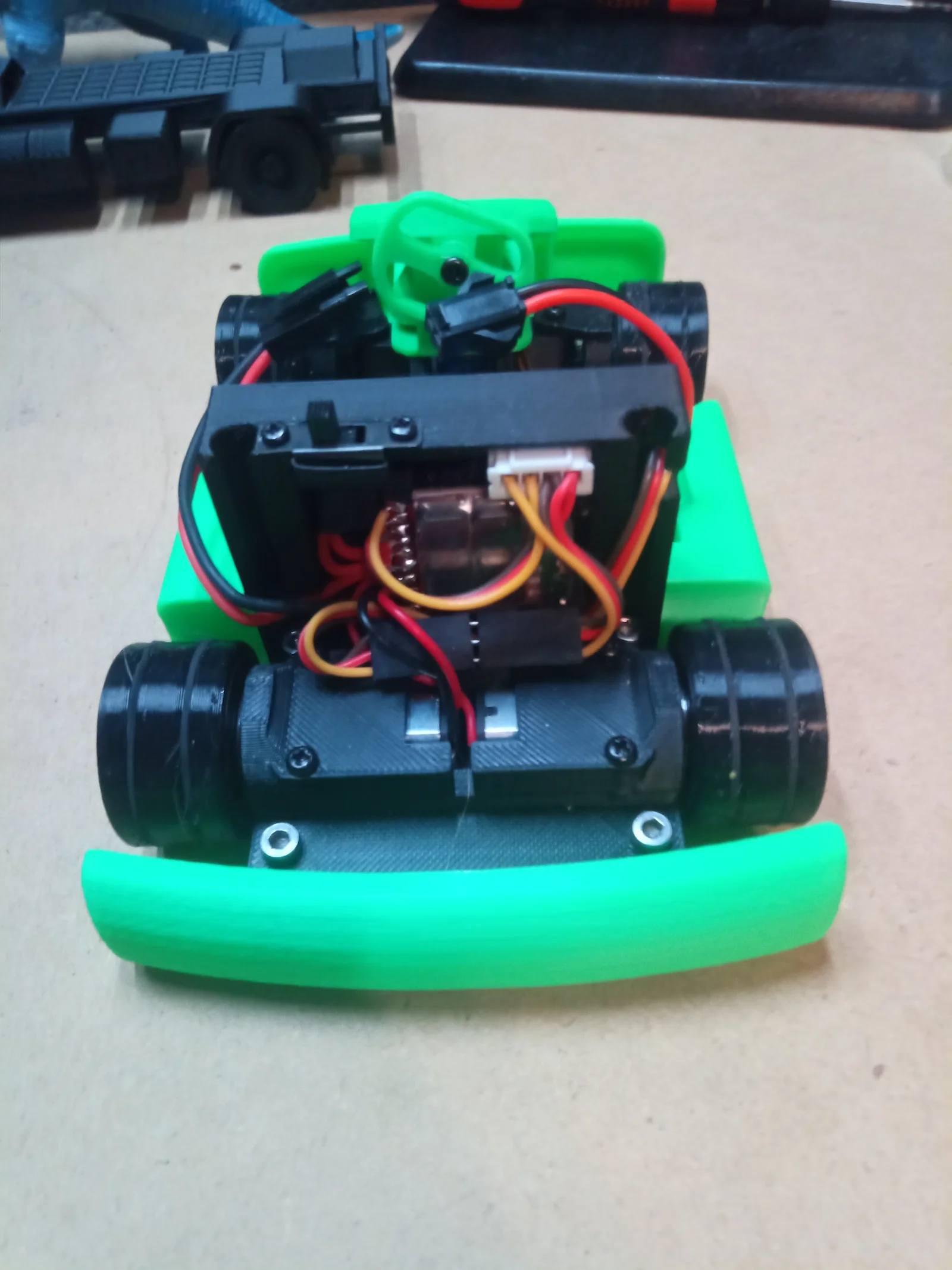
After playing with the gocart for a bit I noticed that the short wheel base and ridged axle made it push really bad when cornering and made the wide steering angle useless as the turning radius limited by the axle, so spent some time thinking on how to add a differential. The simplest solution I could think of with minimal non-printed parts was to add a second motor, allowing the rear wheels to turn independently. This allows tight cornering under power at the expense of some straight-line stability, but requires a pair of motors that match in performance. This also makes centering the front wheels critical so I've uploaded an Arduino sketch I made for using a Bluetooth controller to drive with trim adjustments to fine tune the servo positions. It uses the Bluepad32 board library (https://github.com/ricardoquesada/bluepad32) and should automatically connect with any controller that can connect to Android as a "gamepad". The current configuration uses the left stick to steer and the right trigger for throttle and the left trigger for brake, but there is also an option to use the left stick for throttle/brake. The trim adjustments for the throttle and steering are done by holding top button (Y on Xbox, triangle on PS) and using the D-pad, u-d for throttle or l-r for steering, but it resets every time it's shut off, so any major adjustments should be made by changing the default numbers in the code.
The hardware is only 4x 2.5x8mm screws and another motor. It uses the same bearings as the original axle on the wheels to take stress off the motors since the wheels are attached directly to the motors.
Assembly is done by pressing the bearings on wheels and then pressing the wheels on the motors they are then placed on the axle plate and secured with the axle cover and the 2.5mm screws. be careful not to over-tighten the screws as it can cause the bearings to squish and bind.
Fusion .f3d source file included in a .zip because the upload kept complaining about unsupported compression type.
ByleonicLikes0Downloads1.4K

 ByZED4EverLikes313Downloads5.2K

 ByfifindrLikes500Downloads4K

 ByVC_DesignLikes679Downloads3.6K

 BymoonyxLikes0Downloads698

 ByDan Schwartz SchwartzLikes744Downloads3.4K

 Byvc-designLikes0Downloads3.2K

 Bythorin-oakenshieldLikes0Downloads532

 Bytorii-creative-studioLikes0Downloads450

 ByUpcrid3D_1585693Likes808Downloads2.1K

 ByWilko_SLOLikes935Downloads2K

 ByshoheiyLikes0Downloads430