


Kẹp giữ sợi Filament
 Bytinx_1344834Likes1.2KDownloads6K
Build another version of this model.
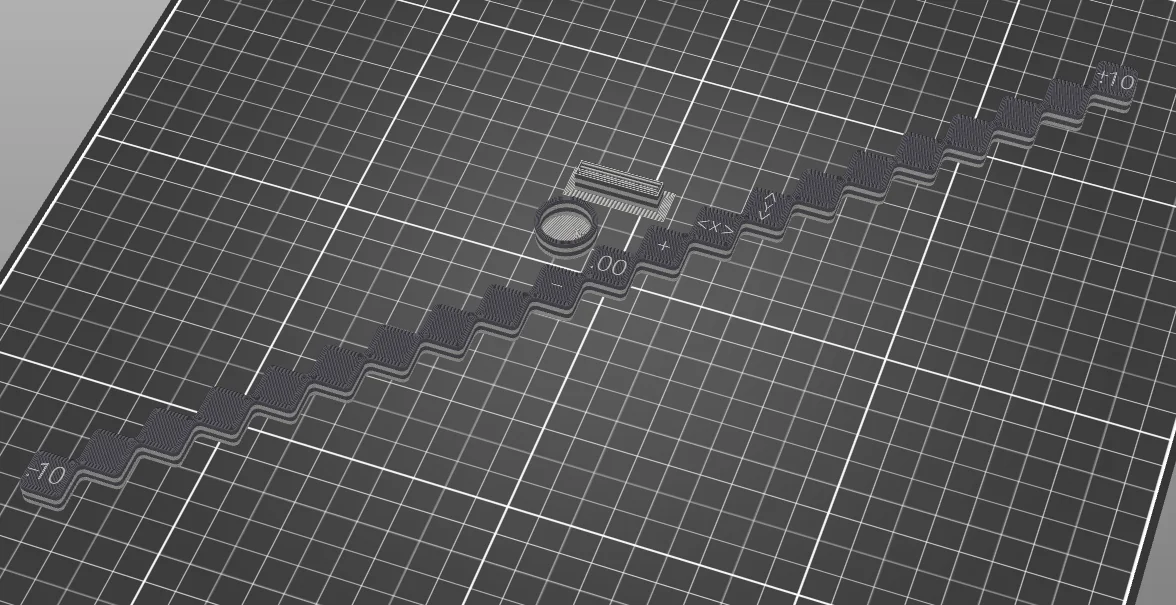
This tool is comprised of four layers. Layers 1 and 3 are intended to be printed with the reference tool (T1 on the XL), while layers 2 and 4 are meant to be printed with the tool to be calibrated. The file is configured to do so automatically using heads 1 and 2. I would recommend printing with contrasting colors if using the same material, or, if you use multi material support for example, the materials you plan to use, to account for different levels of nozzle warping at different temps.
From the center square (marked with .00) the squares on layers 2 and 4 are offset .01mm in X and Y towards the center, resulting in a vernier like pattern that can be easily felt with fingers or calipers, in both directions simultaneously. I have found that the easiest way for me to use it is to clamp the calipers onto a block and check for where the gaps are smallest. Alternatively you can measure each one in turn and find which one is the smallest, with the width being measured changing by ~.02mm between adjacent blocks. Y values are found by comparing top to bottom, while X values are measured side to side (as printed on the tool).
Once you have found the segment that gives the best result for each axis, count how many blocks away from .00 and input that number into the calibration settings on your printer. For Prusa printers you can use the positive or negative values printed on it directly.
P.S. The tower is there to let me see how any seams would look on a part with normal levels of curvature from other angles.
Bytinx_1344834Likes1.2KDownloads6K

 Bynadir-cn3dLikes0Downloads110

 Byprusa-researchLikes0Downloads2.7K

 Bypjs37Likes0Downloads155

 Bygafyx3dLikes0Downloads121

 Byduo3dprintLikes0Downloads153

 BylaserbaconLikes0Downloads172

 ByswimLikes0Downloads109

 Bylk-3d-printsLikes0Downloads207

 Byarhi_585078Likes64Downloads542

 ByleopoldmozartLikes0Downloads136

 By3d-mmakerLikes0Downloads114