



Mẫu gảy đàn Guitar (Guitar Pick) in 3D tùy chỉnh độ dày
 ByWolf_115355Likes513Downloads8.4K
Build another version of this model.
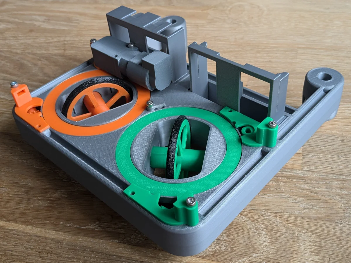
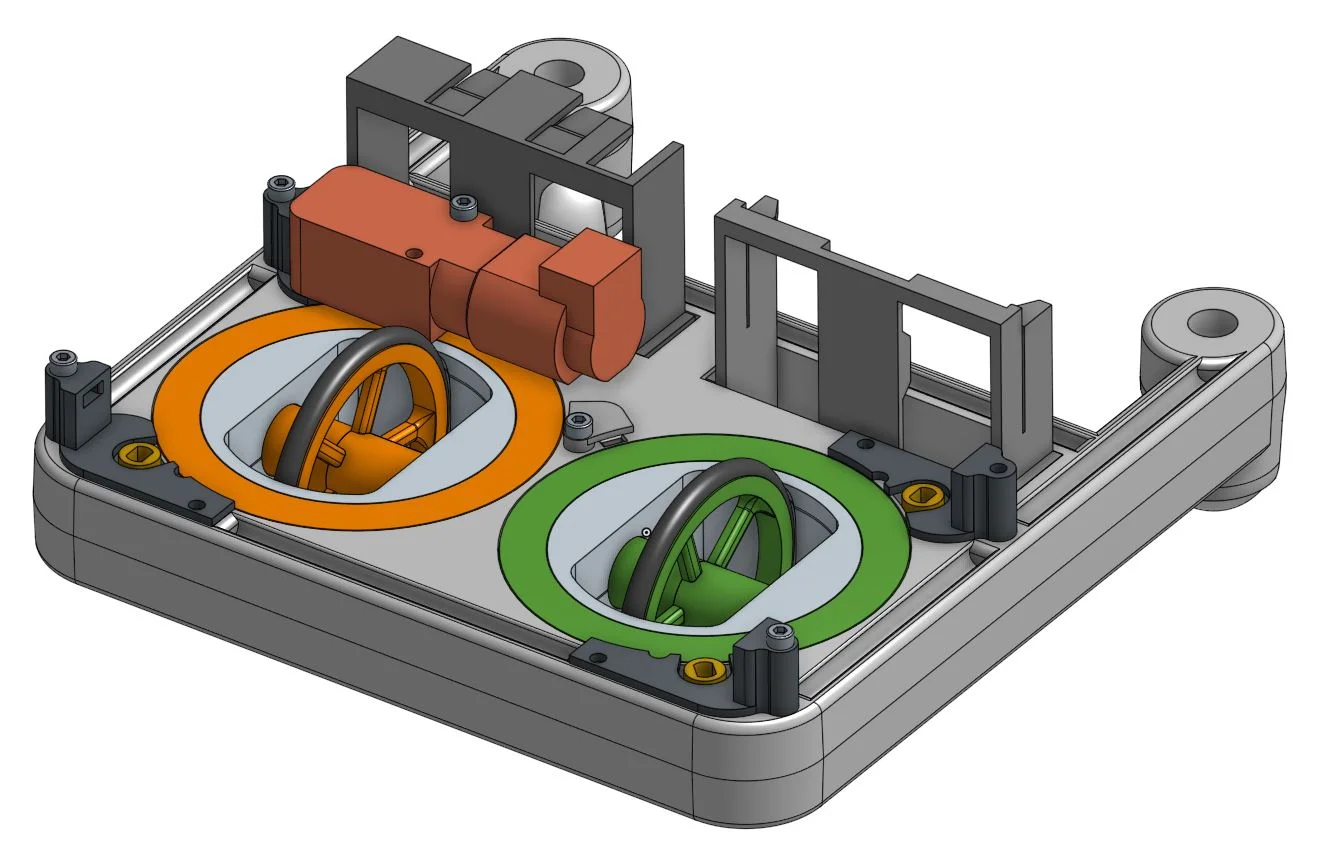
This is a modified XRP chassis with swerve drive modules.
I tried to keep most of the original XRP features, so the size and mounting rails are the same. Both the battery and the controller are mounted in a frame as in the original (however vertical), and the o-ring and the motors are the same.
The swerve drive allows the wheels to spin and change direction by the use of two stationary motors. The rotation of the motors is transferred to the wheel assembly by the use of two gears rotating around the wheel. The model features both a differential swerve (orange) and coaxial swerve (green). The modules look the same from the outside, but are controlled differently.
For an explanation of the differential module see this video:
The coaxial version differs, in that the large lower gear is different. It doesn't have teeth on the inside. So the lower gear is not coupled to the axle of the wheel. Instead, it has a tab, that locks the gear to the inner hub (gray). This means, that the lower gear directly controls the angle of the wheel, while the top gear controls the rotation of the wheel. The section view below shows how the lower gear locks to the hub:
The table below summarizes how many times you need to print each part. Most parts can be printed without support, but I recommend adding tree support for the chassis and the hub-bottom.
Part
Qty for differential
Qty for coaxial
chassis
1
1
gear-differential
4
2
gear-coaxial
0
2
hub-bottom
2
2
hub-top
2
2
gear-bottom-small
2
2
gear-top-small
2
2
wheel-gear
2
2
wheel-axle
2
2
kit-motor-mount-a
2
2
kit-motor-mount-b
2
2
cover-sensor
1
1
mount-battery
1
1
mount-pcb
1
1
Note, that the only difference between the differential and coaxial configuration is the gears. For the coaxial, the bottom gear is different from the differential version.
All model files are provided in stl and step format. You only need one of the formats. Step is easier to modify and also prints nicer.
If you already have an XRP robot and you want to experiment with swerve drives, you only need very few parts in addition to the printed parts.
Part
Qty
Hex socket head cap screw M3x16
9
Hex socket head cap screw M3x20
4
Hex socket head cap screw M3x35
6
Hall sensor A3144
2
Cylindrical magnet 4x5mm
2
Parts in italic are only needed if you want automatic zeroing of the direction of the wheels.
In addition to those parts you will also need some XRP parts: 4 motors (the photos only show one dummy motor mounted), 4 O-rings, 2 castor balls, controller and battery.
If you make remixes of this model and publicly shares the modifications, please consider uploading your changes in an editable format like STEP. It makes it so much easier for others to improve on your changes.
ByWolf_115355Likes513Downloads8.4K

 ByZED4EverLikes313Downloads5.2K

 ByfifindrLikes500Downloads4K

 ByVC_DesignLikes679Downloads3.6K

 ByDan Schwartz SchwartzLikes744Downloads3.4K

 Byvc-designLikes0Downloads3.2K

 ByUpcrid3D_1585693Likes808Downloads2.1K

 ByWilko_SLOLikes935Downloads2K

 Bychubbs8697_2027893Likes585Downloads1.7K

 Byquibeck_3353173Likes965Downloads1.9K

 BySeppoTakaloLikes960Downloads1.9K

 Byadvanced-hobby-labLikes0Downloads288