



Mồi giả câu cá Sardine 120mm
 ByHassanSalehLikes260Downloads2.1K
Build another version of this model.
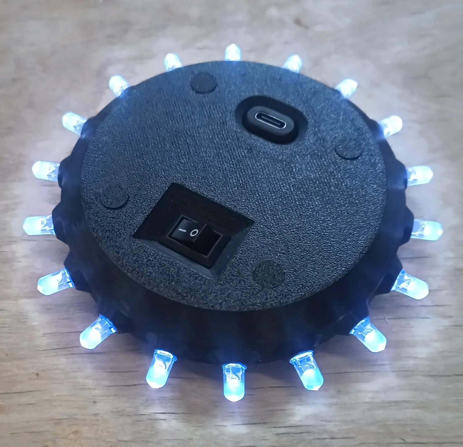
This battery-powered UV light keeps your glow-in-the-dark disc golf discs bright and ready for night play. Shaped and sized like a hockey puck, it fits neatly into your disc golf bag. When powered on, 18 UV LEDs around the circumference evenly illuminate nearby discs, “charging” their glow surfaces so they stay visible during your next throw.
This model may not suit you if you are a regular glow player with a full set of glow discs. You may be better off with various helical or halo models. But if you only have one or two glow discs for winter training, like I do, you will find it useful.
The puck runs from a single 18650 Li‑ion cell and uses a TP4056 charger with MT3608 voltage boost module for efficient recharging via USB‑C. It includes a cradle switch for easy operation. The design features a removable lid secured with small screws for maintenance access. An alternative simplified version omits the screw holes and is intended to be glued shut after assembly. The design requires moderate assembly skills, including soldering and wiring of the LED ring and power modules.
All plastic parts are 3D‑printable; you’ll need to source the following electrical components separately:
1× 18650 Li‑Ion battery (3.7 V)
2× metal AA battery contacts (12×12 mm plates)
1× TP4056 + MT3608 charging/boost module
18× 5‑mm UV LEDs
Suitable resistors (see circuit section)
1× USB‑C socket (12.2×5.2 mm)
1× cradle switch (13.2×9.0 mm)
assorted lengths of wire
4× short 3 mm wood screws (for the lid, optional if using the glued version)
This model is ideal for makers who enjoy a bit of electronics work and want to add a practical, rechargeable UV “glow puck” to their disc golf setup.
The model prints easily in two parts: the base and the lid. No supports are required. The body prints bottom down, the lid prints bottom up. They fit together even on a MINI plate, like the attached gcode file demonstrates. I print in PLA with a 0.4‑mm nozzle and 0.2‑mm layers.
Both screw‑secured and glue‑only versions print identically.
The circuit for the UV Puck is straightforward and uses common hobby components. Power comes from a single 18650 Li‑ion cell (3.7 V nominal), which is charged through a TP4056 charging module. The MT3608 boost converter then raises the voltage to a level suitable for the LED array.
In my version, the LED ring is wired as six parallel branches, each consisting of:
Three LEDs in series (5‑mm UV LEDs rated around 3.2–3.5 V forward voltage and 20 mA forward current)
One 220 Ω resistor in series with them.
The boost module is adjusted to provide about 14 V. This arrangement gives bright and uniform illumination while keeping total current reasonable for battery operation.
You can freely adapt the configuration to match the LEDs and materials you have on hand:
If you have different voltage LEDs, adjust the boost module output so that each branch receives the correct total voltage (about the number of LEDs × forward voltage + 1 V for the resistor).
If you prefer fewer branches with more LEDs, simply recalculate resistor values using Ohm’s law to limit each branch to around 20 mA.
Small differences between LEDs are fine; exact balancing is not critical for this project.
Keep total current draw below about 120 mA–150 mA to maintain good runtime from a single 18650 cell.
The USB‑C connector brings power for charging through the TP4056 board. The cradle switch connects and disconnects the boosted supply to the LED ring. Battery contacts are standard 12 × 12 mm spring and plate types, secured inside the base.
A recommended order of assembly is as follows:
Install the LEDs. Be careful to maintain polarity. If you trust your luck, you may just twist the wires together. It's better to solder them. Remember to keep the branches separate. Electrical tape may come truly handy here. Gluing the LEDs in place is optional and can be done later. Bonus points if you use UV‑activated glue and have the LEDs glue themselves in.
Install battery contacts in the cradle.
Slot in the switch and the USB‑C socket.
Solder or at least twist‑connect all electrical connections:
Battery to charger
USB‑C to charger
Step‑up + terminal to individual resistors
Resistors to LED +
LED − to Step‑up −
Slot in the battery
Test‑run your setup.
Try turning it on and off
Try charging the battery
Cram everything inside the puck. This sounds harsh but at this point only the charger/step‑up module should be hanging out, so find a suitable cavity for it. Make sure you don't short‑circuit anything.
Close the lid. If using the screw‑secured version, take care to set the screw dowels flush with the screw holes in the base.
If using the screw‑secured version, secure the lid with short screws (I use 3‑mm woodscrews 5, 7 or 10 mm long). If using the simplified version, apply a small amount of glue along the rim and press the lid in place.
Go play!
ByHassanSalehLikes260Downloads2.1K

 By3DGearSupplyLikes28Downloads375

 ByCubaLibreee_2869176Likes125Downloads1K

 ByXDr4g0nXLikes198Downloads818

 ByGerhard_48223Likes240Downloads462

 ByBillRichardsLikes32Downloads379

 ByKorriLikes60Downloads609

 ByTarzLikes28Downloads577

 ByMachaki_1134160Likes36Downloads363

 ByMauroVanDerG_4110408Likes378Downloads2.7K

 ByMFTuningLikes153Downloads1.8K

 ByMaverick0197Likes161Downloads1.3K