



Còi Tàu Hơi Nước Mini
 ByfifindrLikes500Downloads4K
Build another version of this model.
Este diseño es uno de los ejercicios de nuestro nuevo curso de diseño 3D avanzado con Fusion.
Info del curso aquí https://control3d.net/curso-de-diseno-3d-fusion-nivel-intermedio/
Suscríbete aquí https://control3d.net/registrate/
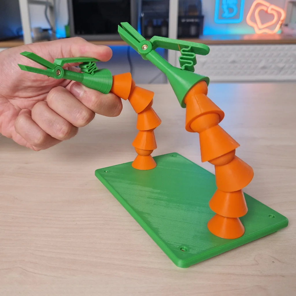
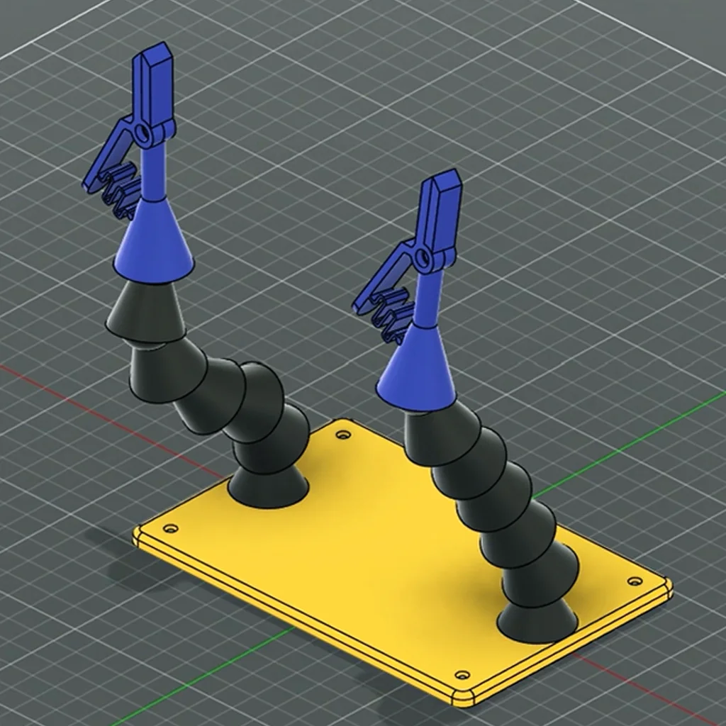
Este soporte para soldadura ha sido diseñado para imprimirse sin soportes.
Lo más recomendable es imprimirlo al menos en PETG, con 4 paredes, o un material que aguante el calor como para ser funcional.
Las patas de la base están impresos en TPU 95A. El modelo tiene tolerancias aplicadas en diseño, aunque siempre teniendo en cuenta las tolerancias de la impresora y el calibrado óptimo del filamento. Las articulaciones entran a presión, y tienen que entrar muy justas, ya que tiene que rozar el material para que mantengan la posición.
Parámetros de impresión recomendados:
Material: PETG o ABS/ASA y TPU
Boquilla: 0,4
Altura de capa: 0,2
Perímetros: 4
Relleno: 10%
Material auxiliar
8 insertos roscados M3x4
6 tornillos M3x6
2 tornillos M3X10
Montaje
Introducimos 4 insertos roscados en la base
Atornillamos las 4 patadas con 4 tornillos M3X6
Colocamos los insertos en las articulaciones base
Atornillamos las articulaciones a la base, con los tornillos M3X10
Encajamos todas las articulaciones entre sí, en 2 grupos de 5. Las articulaciones de la pinza las dejamos para el final
Colocamos los insertos del eje de la pinza
Atornillamos las dos partes de la pinza
Encajamos la articulación de la pinza al resto
This welding support has been designed to be printed without supports.
It is highly recommended to print it at least in PETG, with 4 walls, or a material that can withstand heat well enough to be functional.
The base feet are printed in TPU 95A. The model has tolerances applied in the design, while always keeping in mind the printer's tolerances and optimal filament calibration. The joints snap into place and need to be very tight, as the material must create friction to maintain their position.
Recommended Print Parameters:
Material: PETG or ABS/ASA and TPU
Nozzle: 0.4 mm
Layer Height: 0.2 mm
Walls: 4
Infill: 10%
Additional Hardware
8 x M3x4 heated inserts
6 x M3x6 screws
2 x M3x10 screws
Assembly
Insert 4 heated inserts into the base.
Screw on the 4 feet using 4 M3x6 screws.
Place the inserts into the base joints.
Screw the joints to the base using the M3x10 screws.
Fit all the joints together, making 2 groups of 5. Leave the clamp joints for last.
Place the inserts into the clamp axle.
Screw the two parts of the clamp together.
Fit the clamp joint to the rest of the assembly.
ByfifindrLikes500Downloads4K

 Byquibeck_3353173Likes965Downloads1.9K

 ByVC_DesignLikes104Downloads397

 ByleonicLikes0Downloads1.4K

 ByDan Schwartz SchwartzLikes744Downloads3.4K

 Bykjus_448782Likes314Downloads673

 ByBS_PB_4005052Likes48Downloads143

 ByelitailLikes0Downloads130

 Bychubbs8697_2027893Likes585Downloads1.7K

 Byvc-designLikes0Downloads3.2K

 BywurthLikes0Downloads190

 ByRungeKuttaLikes229Downloads1.2K