



Mẫu gảy đàn Guitar (Guitar Pick) in 3D tùy chỉnh độ dày
 ByWolf_115355Likes513Downloads8.4K
Build another version of this model.
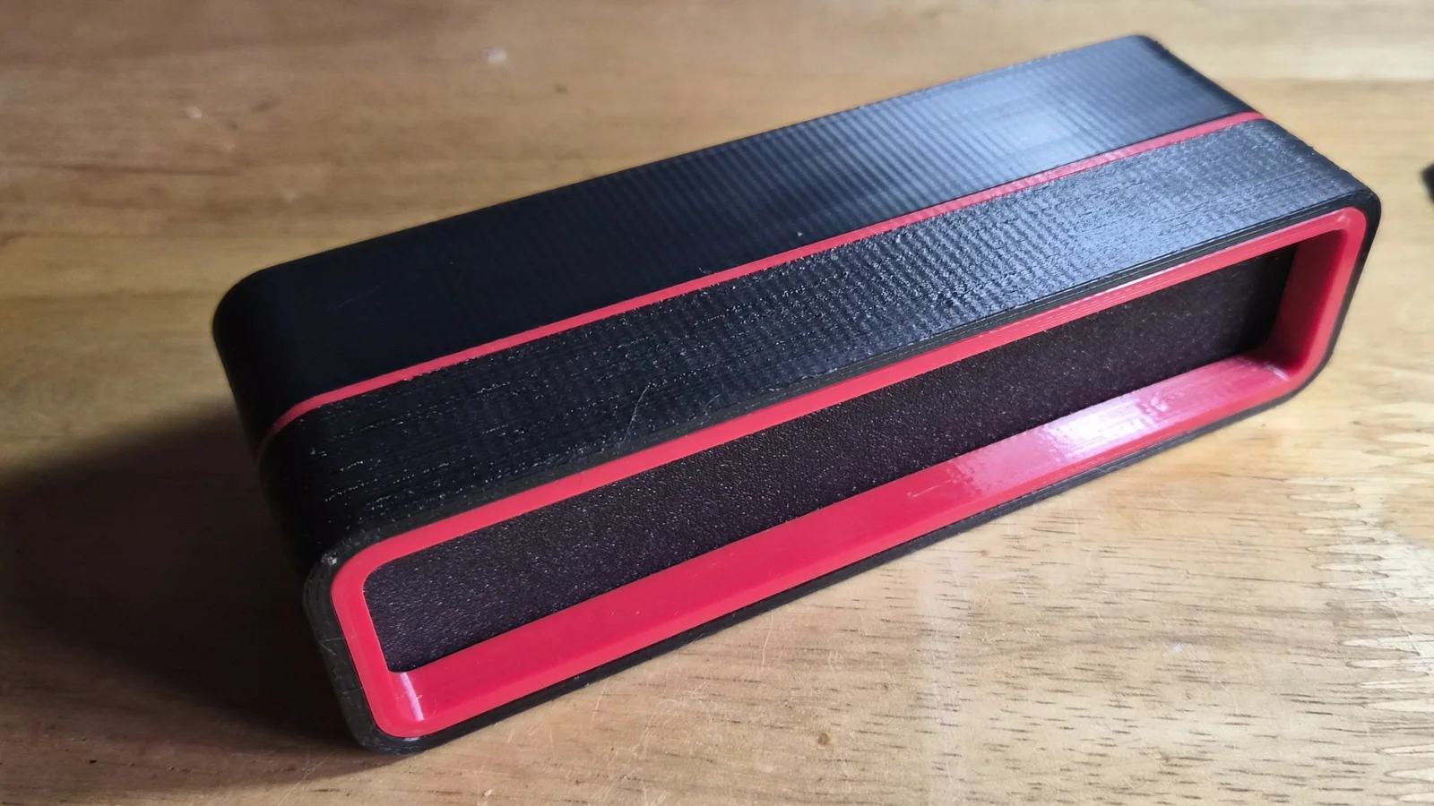
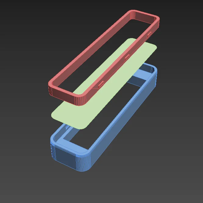
A mostly press-fit clock housing. I've used red and black PETG in my photos but PLA should be fine. I've indicated the colours I used in the part names for reference.
Place the Diffuser on the outside recess of the Case Front
Press the Fascia into the front of the Case Front over the Diffuser.
Place the LED display into the back of the Case Front with the wires attached to the pins and the wires bending outwards.
Place the Screen Support on top of the LED display with the wires fed through it.
Connect the display wires to your ESP32 as needed
Fit the ESP32 into the Case Back. I've used two M3 x 8mm screws but you could glue or sticky-tape it if prefered.
Turn the Case Back upside down and carefully press the 4 rods through the 4 holes of the Screen Support and into the Case Front.
Press together firmly and be careful not to trap any cables!
Updated 24-Feb-2026 - changed the pins on the Case Back to make them slotted with larger radius, so they should grip better.
ByWolf_115355Likes513Downloads8.4K

 ByZED4EverLikes313Downloads5.2K

 ByVC_DesignLikes271Downloads751

 ByfifindrLikes500Downloads4K

 Bymrfixit_324954Likes65Downloads473

 ByDan Schwartz SchwartzLikes744Downloads3.4K

 ByBrokentooth_designsLikes83Downloads448


 Byvc-designLikes0Downloads3.2K

 ByUpcrid3D_1585693Likes808Downloads2.1K

 ByAdam Záhořák ZáhořákLikes39Downloads251

 ByWilko_SLOLikes935Downloads2K