



Mẫu gảy đàn Guitar (Guitar Pick) in 3D tùy chỉnh độ dày
 ByWolf_115355Likes513Downloads8.4K
Build another version of this model.
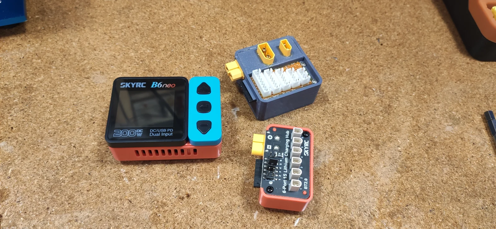
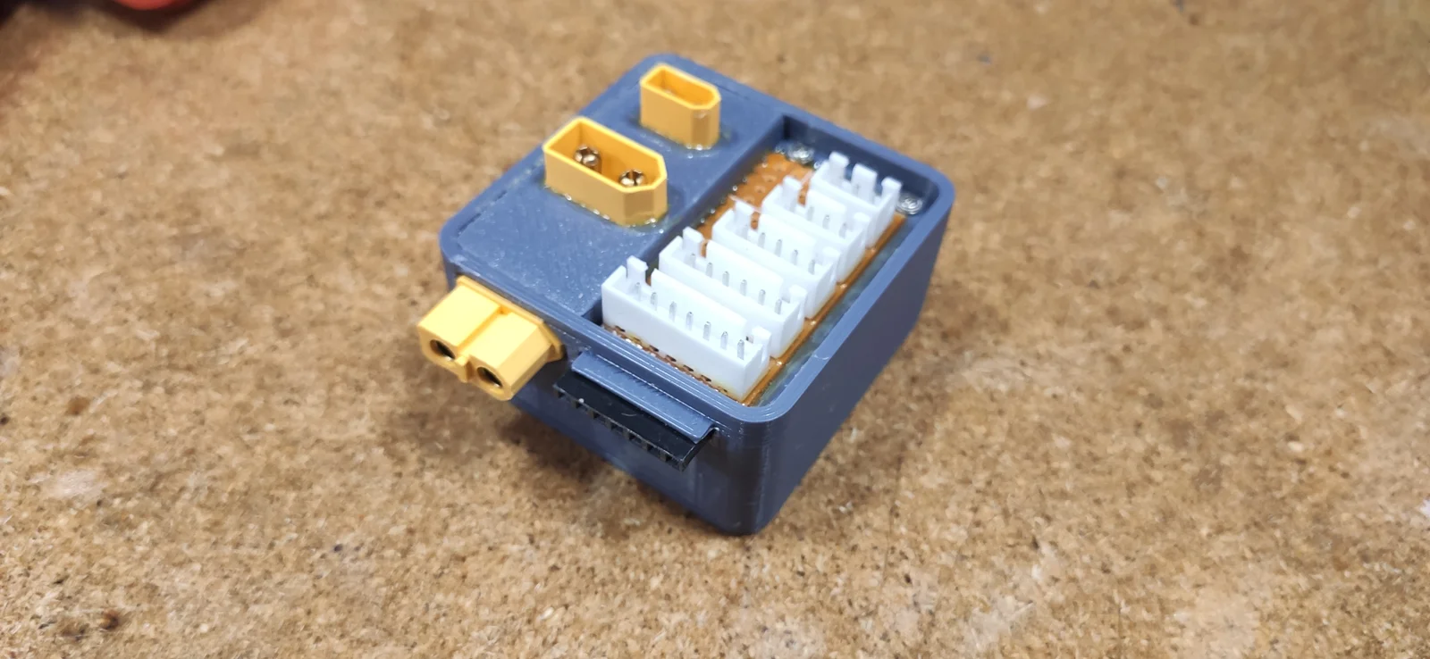
The adapter module for the sophisticated RC dude who does not want to carry around a mess of adapter cables. /s
I printed mine in pla+, but a more heat-resistant material would probably be preferable.
Parts list:
1 - XT60 male
1 - XT60 female
1 - XT30 male
1 - 7-pin female pin header
1 - JST connector, one each for 2S-6S
1 - strip grid PCB piece 14 - 15 holes long, 7 wide
2 - cable pieces
2 - 1.5mm screws
4 - M3 threaded inserts
4 - M3 countersunk head screws
Instructions:
The support for the lip for the balance plug is built into the model and must be cut away after printing.
Four M3 countersunk head screws hold the bottom cover in place; threaded inserts are fused into the housing for this purpose.
The plugs are quite tight, and the +- symbols on the side of the XT plugs need to be sanded off.
Use the soldering fixture to solder the connectors before installation.
The balancing PCB consists of JST connectors, strip grid PCB and a female pin header.
Liberally apply E6000 to the plugs and balancing PCB when installing them in the housing.
Secure the balancing PCB with a few 1.5 mm screws, ensuring that no conductor tracks are short-circuited.
Install the cover with the plugs that have already been soldered and glued. Secure it from below with a little E6000.
Fit the bottom cover and you're done.
ByWolf_115355Likes513Downloads8.4K

 ByZED4EverLikes313Downloads5.2K

 ByfifindrLikes500Downloads4K

 ByVC_DesignLikes679Downloads3.6K

 ByDan Schwartz SchwartzLikes744Downloads3.4K

 Byvc-designLikes0Downloads3.2K

 ByUpcrid3D_1585693Likes808Downloads2.1K

 ByWilko_SLOLikes935Downloads2K

 Bychubbs8697_2027893Likes585Downloads1.7K

 Byquibeck_3353173Likes965Downloads1.9K

 BySeppoTakaloLikes960Downloads1.9K

 Byadvanced-hobby-labLikes0Downloads286