
Đồng hồ Kỹ thuật số Cơ khí (24 giờ)
- Downloads
- 560
- Likes
- 451
- Views
- 11,246
- Remixes
- 0
- Comments
- 0
Files 15 25.9 MB
- gearbox_1767169358.STLSTL · 4.8 MB
- gearbox_cover_1767169359.STLSTL · 1.3 MB
- bottom_cover_1767169360.STLSTL · 2.2 MB
- separator_1767169361.STLSTL · 785.6 KB
Make a variant with AI
Build another version of this model.
Details
- Model ID
- #183964
- Category
- Giáo Dục
- Published
- License
- Creative Commons — Attribution
Description
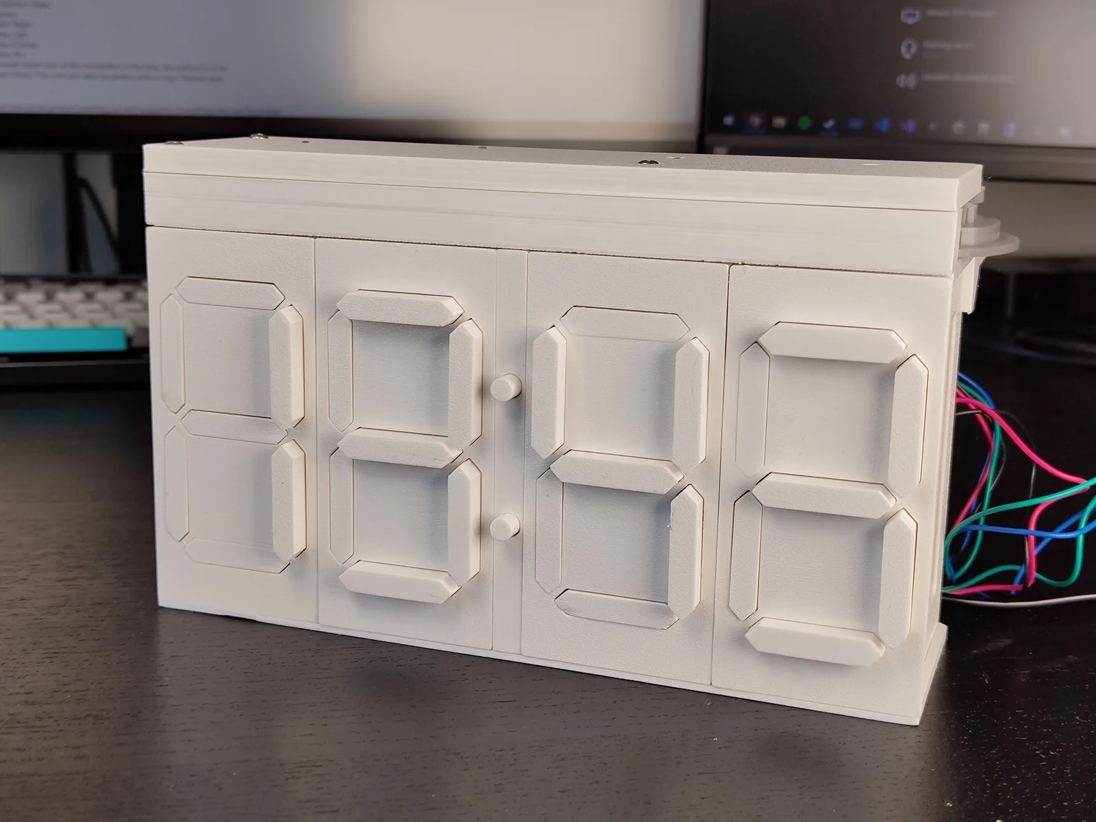
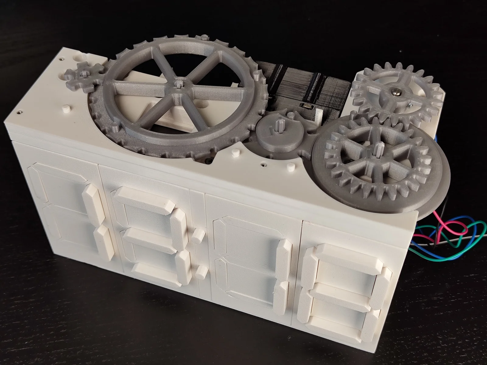
This is a mechanical digital 24-hour clock. It is driven by a single motor (or by hand) and uses geneva drives and camshafts to display the correct patterns on four mechanical seven segment displays.
Non-printed parts
- 46x Square M3 nuts
- 50x M3x6 screws (or longer)
- Plastic glue
- Electronics (see below)
Digits
In addition to the files in this model, you need to print four mechanical seven segment displays. From left to right, the digits are:
- Seven Segment Display with the
cam_0-2_CW.stlcamshaft - Large 24h Seven Segment Display with the
cam_0-23_CCW.stlcamshaft - Seven Segment Display with the
cam_0-5_CW.stlcamshaft - Seven Segment Display with the
cam_0-9_CCW.stlcamshaft
Motorization and electronics
The electronics setup for the motorization will depend on which particular parts you want to use. I provide some information about my setup for reference but this is not a comprehensive tutorial. The motor mount part fits a Nema 17 stepper motor and the electronics enclosure fits a 400-point breadboard. These are the parts I used:
- Seeduino XIAO
- Nema 17 Bipolar 1A 13Ncm 42 x 20mm Stepper Motor
- TMC2209 Stepper Motor Driver
- 12V 2A Power Supply with a 5.5 x 2.5mm DC Plug
- LF50CV voltage regulator to power the Arduino
- push buttons and pull down resistors
Assembly
- Attach two dots to the separator with glue. Insert four square nuts and glue them in place.
- Insert 3 square nuts into the gearbox
- Place the four digits next to each other
- Put the gearbox on top of the digits and insert 8 screws
- Place the separator between the digits and attach it with 2 screws
- Turn the assembly upside down and attach the bottom cover with 10 screws
- Insert 2 square nuts into the motor mount
- Attach the motor to the motor mount with 4 screws
- Attach the motor mount to the gearbox with 2 screws
- Use an axle to turn all four digits to 0. The second display has 3 different zeros, you need the one that comes after a 3.
- Put down the four gears and make sure that the alignment line points to the front
- Place an axle into each gear
- Insert a square nut and a screw into the motor gear, but don't tighten the screw
- Attach the motor gear and tighten the screw
- Optional: Electronics box
- Insert 5 square nuts into the bottom part of the electronics box
- Place a breadboard with all your components into the boxHere is another photo for wiring details:
- Attach the top cover with 3 screws
- Push it into the main assembly and attach it with 2 screws
- Put the top cover on the gearbox and fasten it with 3 screws
Print spec
- Formats
- inostl
- Model files
- 15
- Total size
- 25.9 MB
- Largest file
- 9.1 MB
0 comments
You may also like 12 models
See all-

-

-

-

-

-
New -

-

-

-

-

-