



Bộ sưu tập ray Picatinny và kẹp lắp đặt cho mô hình in 3D
 ByMFTuningLikes153Downloads1.8K
Build another version of this model.
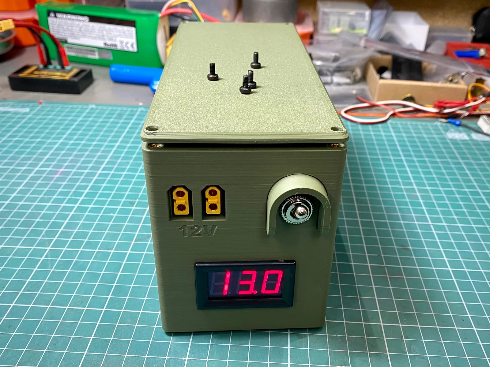
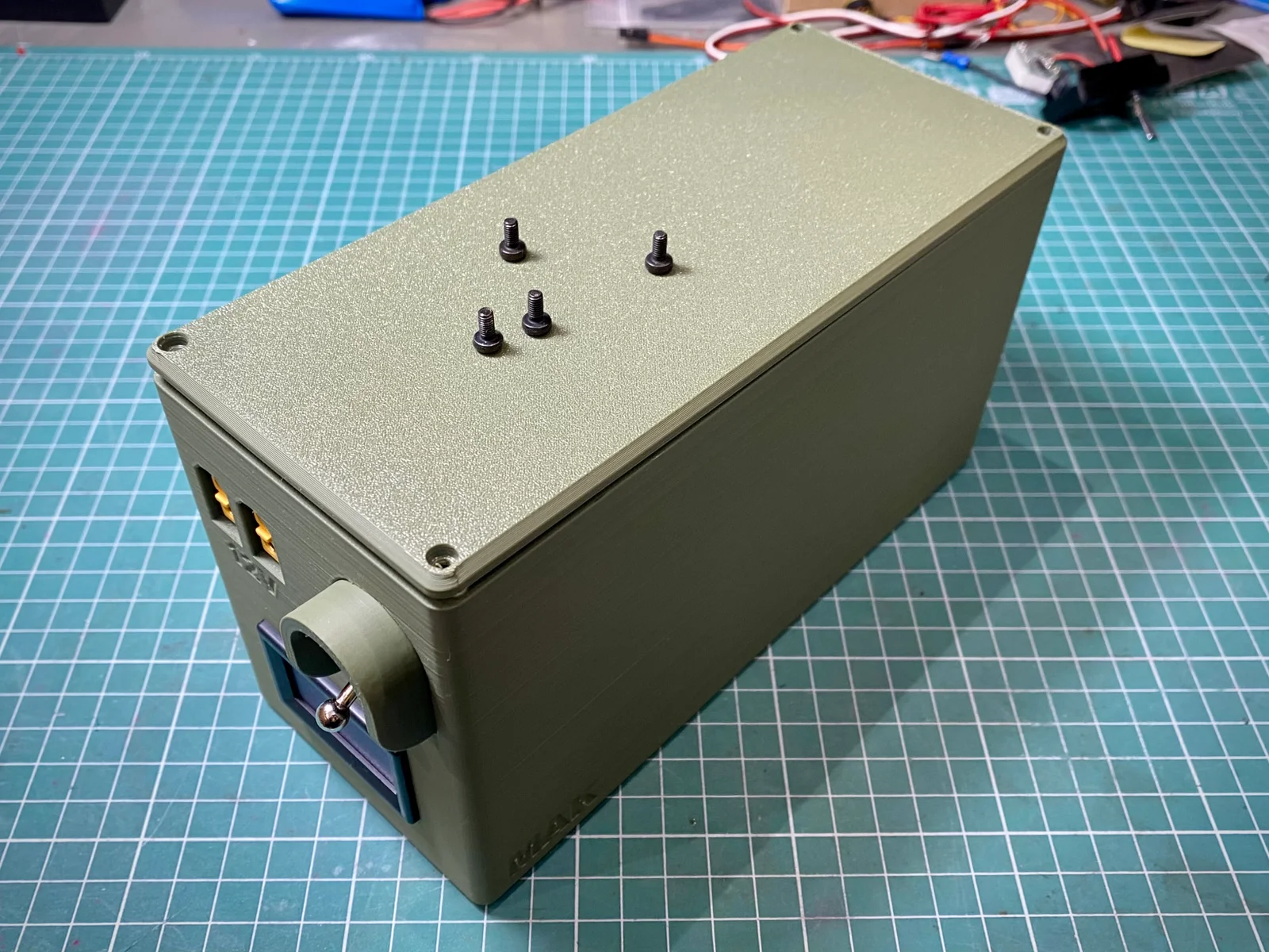
12V Pb power bank, ideal to drive 12V COB LED light strips, i.e. in a gun safe internal installation, where no other power source may be available and the safety is valued.
Pb battery is much more safer than modern LiIon/LiPo batteries – due to significantly less fire-hazard involved, which is important when installed inside of a gun vault where firearm ammunition is stored. 7Ah capacity should be more then enough for many weeks of even months of short, not very frequent use (as it is in case of a gun safe usually; extended 9Ah capacity batteries are also available).
I recommend getting AGM deep cycle battery, which can be safely discharged to low levels (getting the most of its nominal capacity). Absolute minimum for such 12V batteries is typically 10.5V, however I would not go lower than 11.5V to keep the battery healthy and lasting long (check your battery specs though).
Magnetics cable hooks / organizers visible on one of the photos will be published on my Printables profile shortly. Stay tuned or simply follow me to get notified.
Straight forward, no supports needed if rotated properly on a bed (except for the voltmeter mounting hole overhang; but even there you may print it without supports as the voltmeter has a frame which will hide any bridging imperfection once installed).
ByMFTuningLikes153Downloads1.8K

 ByMaverick0197Likes161Downloads1.3K

 ByMauroVanDerG_4110408Likes378Downloads2.7K

 ByAdamSwintLikes83Downloads337

 Byclad-coral2Likes0Downloads364

 ByHPFanLikes0Downloads10

 ByCubaLibreee_2869176Likes125Downloads1K

 By3d-finesseLikes0Downloads141

 ByDylanBermejo_3971567Likes12Downloads107

 ByXDr4g0nXLikes198Downloads830

 By3DMasonLikes0Downloads111

 ByCreativeKari_4457452Likes10Downloads78