



Bộ sưu tập 11 nhân vật mô hình Mecca Chameleon in 3D vui nhộn
 ByZED4EverLikes313Downloads5.2K
Build another version of this model.
 Vỏ hộp (case) in 3D cho Raspberry Pi 3 tản nhiệt tốtByJetsteam_1342094 · 04/13/2026
 Giá treo tường cho Raspberry Pi5 + Geekworm X1001 NVMe SSD CaseBySidebySide_4442039 · 03/01/2026
 Vỏ Raspberry Pi 5 + Geekworm X1001 NVMe SSD (bản đã chỉnh sửa)Byreboot_1578528 · 02/12/2026
 Vỏ Raspberry Pi 5 + Geekworm X1001 HAT + NVMe SSDByCrooksUSA_454719 · 01/05/2026
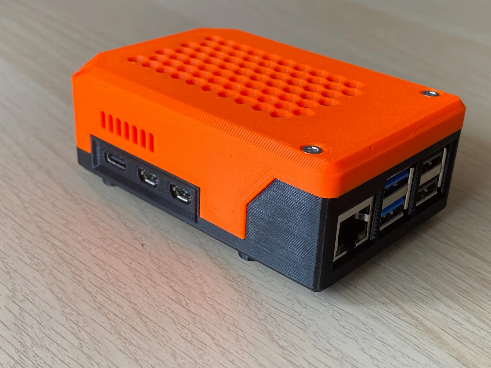
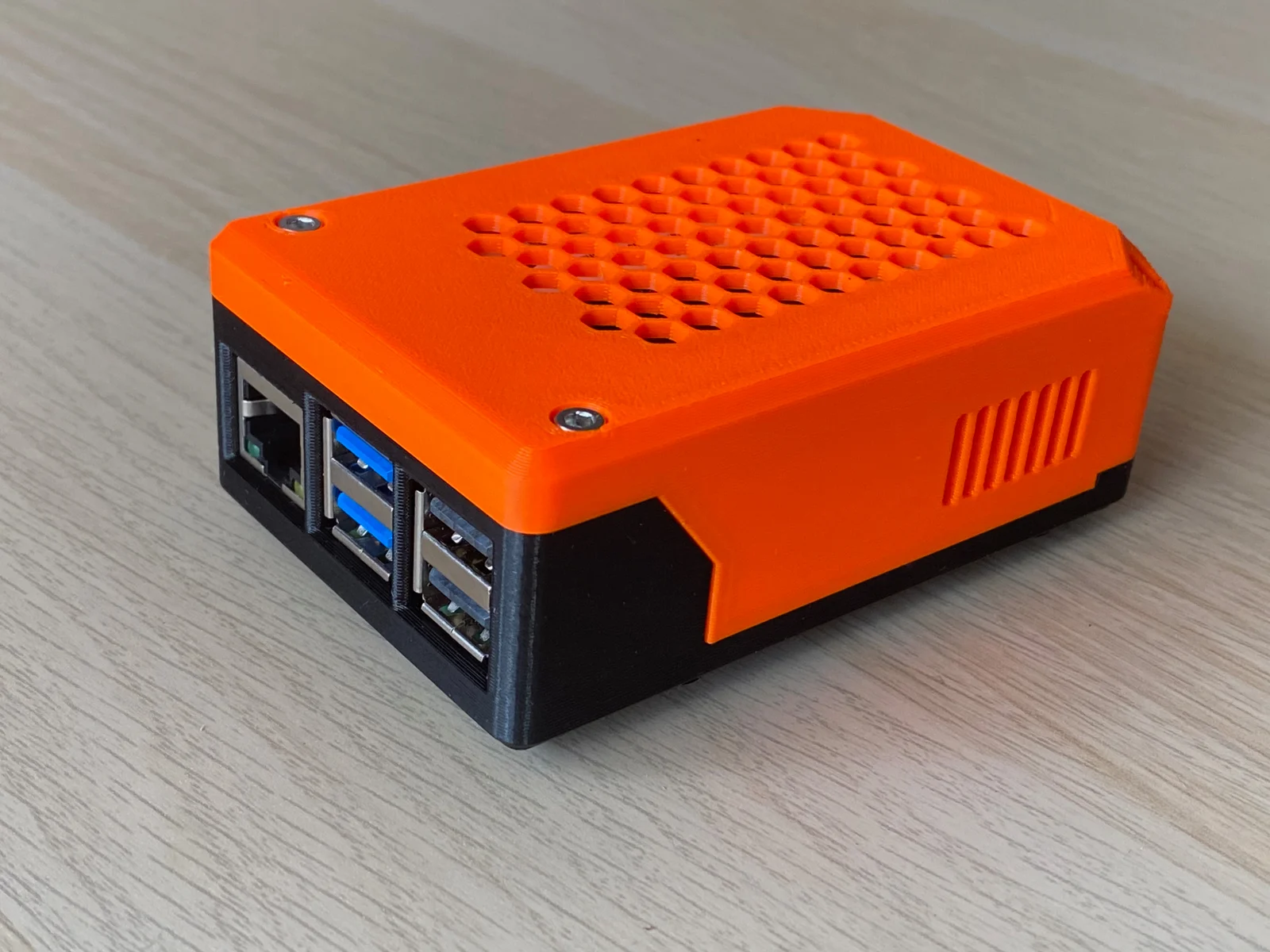
This model was inspired by another model https://www.printables.com/model/924041-raspberry-pi-5-case-with-pineberry-hatdrive-bottom, but it's not a remix. The case was designed completely from scratch (no reverse engineering).
The case was designed to fit the Raspberry Pi 5 with the mounted Geekworm X1001 shield for the NVME M2 SSD (https://wiki.geekworm.com/X1001). The following features were implemented:
The table below shows the print settings used to print the model.
Property
Value
Filament
PETG, ABS
Infill
20%
Walls
3-4
Top/bottom layers
4
Layer
0.2
This section contains some additional information about the design.
One of the holes in the lower part (see image below) was intentionally designed with a smaller diameter. It is only used for bottom spacer (stand) mounting and does not participate in board fastening. Because it is screwed into plastic directly, the hole diameter was reduced for improved rigidity of the screw fastening.
The power button contains a hole that could be filled with hot glue to serve as a light conductor and make the button display the system's current status.
ByZED4EverLikes313Downloads5.2K

 ByVC_DesignLikes271Downloads753

 Byfoprel_1853178Likes1Downloads6

 ByfifindrLikes500Downloads4K

 Bymrfixit_324954Likes65Downloads473

 ByDan Schwartz SchwartzLikes744Downloads3.4K


 ByBrokentooth_designsLikes83Downloads449

 Bytomi-oneLikes0Downloads233

 Byvc-designLikes0Downloads3.2K

 ByKNIN_CustomLikes112Downloads437

 ByUpcrid3D_1585693Likes808Downloads2.1K