




Kẹp giữ sợi Filament
 Bytinx_1344834Likes1.2KDownloads6K
Build another version of this model.
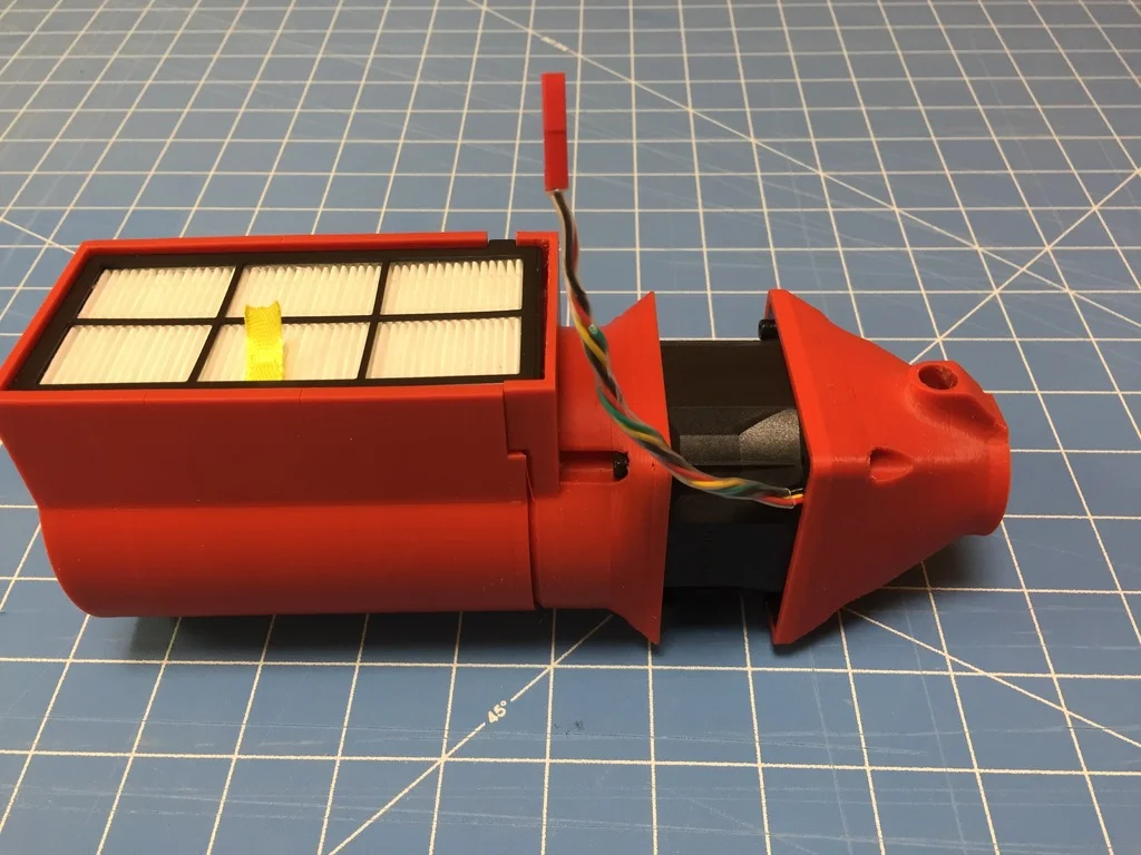
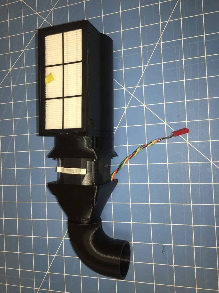
Air Scrubber for 3D Printers
The_Prusa i3 MK2S_ is a great printer especially for the hobbyist or light industrial desktop user. That having been said it is a raw printer without a lot of accessories that would make it a great printer. The is the first in a series of accessories that I designed for the_i3_. The others are:
https://www.thingiverse.com/thing:2396990
https://www.thingiverse.com/thing:2398480
https://www.thingiverse.com/thing:2401423
This accessory is intended to remove VOC and Ultra Fine particles from the enclosure housing the printer.
3D Printers produce VOC and Ultra Fine particles as a unwanted byproduct of melting and extruding plastics. See recent study by Illinois Institute of Technology and The University of Texas at Austin among others: http://pubs.acs.org/doi/full/10.1021/acs.est.5b04983
Additionally some filaments emit a noxious odor when heated to high temperatures.
Originally the plan was to exhaust 100% of the filtered air either inside the enclosure (moisture elimination & heat retention) or outside the enclosure if internal ambient temperature was not a concern. The exhaust configuration could be changed prior to each print. After several experiments it was determined that a portion of the filtered air (about 40%) should be recirculated and the remainder ported outside the enclosure. By porting a portion of the filtered air outside the enclosure, the pressure inside the enclose is lower compared to ambient. This insures that no unfiltered air escapes from the enclosure during printing. The current_Nozzle_ design accomplishes this. Included is a_Restrictor_ plate to change the mix to 50/50% should the 40/60% cause the enclosure temperature to drop too much when printing ABS or other filament types that require a high stabilized temperature.
The design includes a_Extended Grate_ that can be used to divide the chamber into two sections, one for silica (drying) and one for activated carbon pellets (VOC filtering). In practice it was found that the_Activated Carbon Pellets_ provided adequate anhydrous characteristics and silica was not needed. Should your experience vary, simply insert the_Expanded Grate_ at an appropriate location in the chamber. Fill the section closest to the_Fan_ with_Activated Carbon Pellets_ and the other with Silica. This insures all the air is filtered for VOCs.
This assembly is based on a design by RJ_Make that incorporates a HEPA filter originally designed for iRobot sweepers and a chamber which contains_Activated Carbon Pellets_. This remix differs from the one by RJ_Make:
7/12/2017 Update: Removed file "Chamber Top" as it is no longer needed.
1/7/2018 Update:
3/5/2019 Update:
Added Strengthened Mount courtesy of beikeland.
Printer:
Prusa i3 MK2S
Rafts:
No
Supports:
Yes
Resolution:
0.20
Infill:
20%
Notes:
PLA or ABS may be used to print the various parts.ABS orPETG should be used If ambient temperature willexceed 55°C.
The Tg (Glass Transition Temperature) for Materials:
Main Body
The main body consists of two parts:
These two parts are joined together using epoxy, super glue, or hot glue. Care should be taken to properly align both parts so that the HEPA filter can be easily inserted into the top of the resulting assembly. The assembly could have been printed as one part but that would have resulted in excessive support material on the grate at the top of the chamber.
Prepare Nozzle & Chamber to Fan Captive Nuts
These parts contain nut wells suitable for retaining lock nuts the M3x14 screws use to hold these parts to the fan. The nuts must be inserted into the parts before the fan is attached to each in turn. The best method to do this is to temporarily insert a screw of suitable length into the fan side of the part (without the fan installed) and to start the nut on the screw. The Nut can then be properly seated by tightening the screw or by gently taping the nut with a nail set approximately the same size as the nut. Once the nut is seated, remove the screw.
Prepare Fan for Installation
A_High Static Pressure Fan_ is required to force air through the Carbon pellets at an acceptable flow rate. The Fan used (See BOM) was chosen for its form factor (60x60x38mm), CFM flow rate, and cost. This fan was originally used in a Dell computer and is a 4 wire system. The fan is delivered with a connector that would normally plug into the Dell motherboard. Remove this connector. Wire the RED and BLACK wires to the Male Connector as shown below. Note the Red Wire is on the left when observed from the pins side of the connector. Cap and stow the Green & Yellow wires. They are not used in this installation.
CAUTION
This motor is extremely polarity sensitive. Reversing the Fan motor willdestroy the unit!
Install Fan & Exhaust Tube
Install Fan into the mating parts using 4 screws in each assembly. The_Fan_ and_Nozzle_ can be rotated into any of 4 positions. Rotate the_Fan_ so that the power wire is positioned as required for your installation. Likewise rotate the_Nozzle_ so that the recirculating air port does not blow air on the print bed but is otherwise unobstructed.
Install the_Exhaust Tube_ to the_Nozzle_. This is an interference fix. Make sure that no extruded plastic is obstructing the_Exhaust Tube_ opening or the_Nozzle_ flange. The_Exhaust Tube_ should be able to rotate once installed but should not be so loose that it falls off the_Nozzle_. See completed assembly below.
HEPA Filter Assembly
Optional Fan Speed Control
The Fan can be operated at 100% rated speed by simply plugging the connector into a 12Vdc power supply. However there are often times a slower fan speed is desirable. For these cases a Speed Controller can be used to throttle down the Fan speed and therefore the filtered air volume.
Originally it was thought that the speed control potentiometer would be best located away from the speed control board and that the control board incorporated into the filter body. This proved impractical and the control board and potentiometer are now housed in a separate box with the output wired to the_Fan_ through a mating connector to the one installed on the_Fan_ in the steps above. Files necessary to print the_Control Box_ top and bottom are included in the files section.
An alternate speed control is available with the potentiometer incorporated on the control board. The alternate part is listed below in the BOM. This would require a modification to the included_Control Box_ since the size required is somewhat less and the potentiometer and control board are positioned differently.
Control Board wiring is identical for either version of the control board. See below.
Caution
The control board polarities are critical. Reversing the polarities can damage the_Control Board_ and_Fan_. For this installation the input voltage_must_ be 12VDC.
Speed Control Board Wiring
Filter Mount
The mount below is designed to be screwed on to a vertical surface.
Filter Wall Mount
Installation in Prusa i3 MK2S Enclosure
The picture below shows the HEPA Filter mounted in the Prusa i3 MK2S enclosure. Note the positioning of the_Mount_,Exhaust Tube, and power wire. Not visible is the_Nozzle_ recirculating vent which is pointed down. Also note the_Fan_ to_Speed Controller_ connector that is just visible under the top i3 Support bar.
1/7/2018 Update
Assembly Instructions
Additional Supported Fans
Two additional fans have been added to the BOM to provide for varying levels of noise and airflow:
Fan Part Number RPM CFM Noise Length Noctura NF-A6x25 FLX 3000 17 19Dba 25mm Sunon PMD1206PMB3-A 6000 42 47Dba 38mm San Ace 9G0612G101 11,800 65 58Dba 38mm The Noctura fan is virtually silent but the airflow is not sufficient to purge the_Enclosure_ in real time. After printing PLA for an hour, one additional hour was required to remove all noticeable odor from the_Enclosure_. The airflow does appear to be sufficient to create a slight vacuum in the_Enclosure_ therefore trapping the nono-particles within the_Enclosure_. Temperature rise withing the_Enclosure_ was modest, rising only 5°C to 35°C with a bed temperature of 60°C. Care should be exercised in not opening the_Enclosure_ door for a period of time in order to allow all the nono particles that can be removed to be removed.
The Sanon fan is sufficient for most applications. The noise level is only noticeable when the printer is not running. The Prusa i3 MK2S Hot End cooling fan drowns out the sound of the Sanon fan during printing operations.
Finally the San Ace fan should be used where maximum airflow is required to lower the_Enclosure_ temperature.
Bill of Materials
https://www.amazon.com/gp/product/B0143GZU4W
https://www.amazon.com/gp/product/B01N90UFNA
High Static Pressure Fan:
https://www.amazon.com/gp/product/B009NQMESS
https://www.amazon.com/gp/product/B00608LYVK
https://www.digikey.com/product-detail/en/sanyo-denki-america-inc/9G0612G101/1688-1409-ND/6192125 - 4 ea M3x60mm Screws for installation of the San Ace Fan. https://www.amazon.com/gp/product/B076XKGNDB
Fan Speed Controller
https://www.amazon.com/gp/product/B00RYKR83Q or https://www.amazon.com/uniquegoods-Controller-1803BK-Adjustable-Driver/dp/B00QGMESHM
https://www.amazon.com/Hilitchi-300Pcs-Housing-Terminal-Connector/dp/B0188YKCFC
https://www.amazon.com/MZY-LLC-Filters-Replacement-Robotic/dp/B00K7DMEJ0
https://www.amazon.com/gp/product/B000YIWT20
https://www.amazon.com/Premium-Desiccant-Indicating-Industry-Standard/dp/B01I5Y2DG6
Category: 3D Printer Accessories
Bytinx_1344834Likes1.2KDownloads6K

 Byarhi_585078Likes64Downloads542

 ByHanzo3dLikes155Downloads415

 ByGeek5DLikes147Downloads485

 ByBrokentooth_designsLikes23Downloads409

 Bycrawler-3903250Likes0Downloads907

 By3DSourcererLikes48Downloads377

 Byartme-3dLikes0Downloads334

 Bybloblis67Likes0Downloads318

 ByWyomingWolf_261196Likes52Downloads430

 Byprusa-researchLikes0Downloads2.7K

 Byzachstofko_3956201Likes88Downloads162