F3D
Giá đỡ laptop phía sau màn hình 1

1 image

Dụng Cụ Tiện Ích

Giá đỡ laptop phía sau màn hình

By aiber

Downloads
60
Likes
19
Views
3,094

Files 11 11.5 MB

  • ARM_SIDE_MOUNT_0.3mm_PLA_MK3S_2h59m_1765624122.gcodeGCODE · 3.9 MB
  • REAR_MOUNT_HP_L2245WG_0.3mm_PLA_MK3S_3h55m_1765624123.gcodeGCODE · 5.9 MB
  • REAR_MOUNT_HP_L2245WG_PROJECT_1765624115.3mf3MF · 123.4 KB
  • HOOK_ADJUSTABLE_1765624116.stlSTL · 49.1 KB

Make a variant with AI

Build another version of this model.

Open Studio

Description

  • for use with a VESA pattern monitor
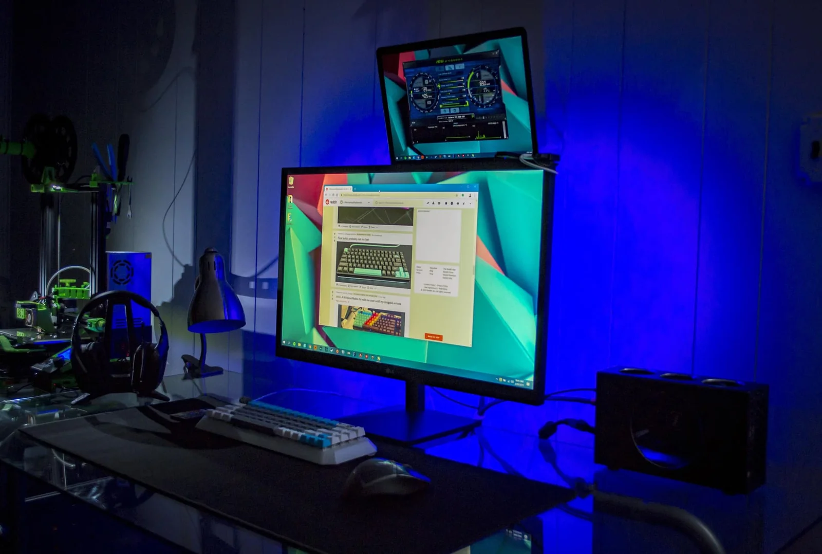
  • in my case I needed to mount my laptop behind a monitor with the laptop's screen exposed as an addition monitor
  • the monitor was an HP L2245WG (22", I think) which had its own stock monitor stand I needed to work around
  • I don't think I have any pictures of it in real life, but it worked fine in PLA & was plenty strong - similar pictured attached
  • uses M4 hardware to piggyback to the monitor, M4 x 30 mm IIRC
  • adjustable arms compensate for thicker or thinner laptops (I used it with a Dell Precision 7540, which is fairly thick)
  • I used a piece of cardboard to avoid marking up the trackpad & triggering the keyboard
  • vertical adjustment features to allow laptop screen to be positioned wherever you like relative to the center of the VESA mount - logically so that the bezel of both screens line up
  • I was going to improve the design & CAD, but gave up because I have better things to do now

2024-01-28 rev 7 assembly instructions

Here is a view of the assembly, only one side:

  • I was too lazy to mirror the components
  • note that I'm pretty sure I never tested, let alone printed rev 7 parts
  • when you print the parts, you'll have to mirror 2 of the 3 unique parts, the HOOK & the ARM

All the hardware is M4:

  • I put down qty 3 nylock nuts
    • qty 2 for adjusting the HOOK in its slot relative to the ARM in order to accommodate laptops of different thickness
      • I used a piece of cardboard on the keyboard side to mitigate damage to the keys
    • qty 1 to lock the ARM vertical adjustment relative to the MOUNT
      • the idea behind rev 7 was to reduce the fastener count on this joint by leveraging the edge which already existed as a sort of sliding rabbet joint

MOUNT

  • The mount has a square hole pattern for a VESA 100 x 100 mm mount, also using M4 hardware IIRC
    • the corner holes are reserved for that purpose
    • the holes in the vertical row are for fine tuning the adjustment of the ARM up & down to position the laptop screen wherever you'd like within reason
  • The reason why it's a U shape is because my monitor at the time was some HP L224G monitor or something & I wanted this stand to work with the existing desk stand that came with the monitor
  • Therefore, I needed this U shape to reach around that stand to utilize both simultaneously
  • If you had a generic VESA stand, this part might still work

Read more Show less

Print spec

Formats
3mfgcodeiptstl
Model files
11
Total size
11.5 MB
Largest file
5.9 MB

0 comments

See all