



Mô hình đường ray thẳng Lego City Train tự in 3D cực tiện lợi
 ByChristianS_2237751Likes502Downloads3.7K
Build another version of this model.
Section One: The Robotic Arm Assembly
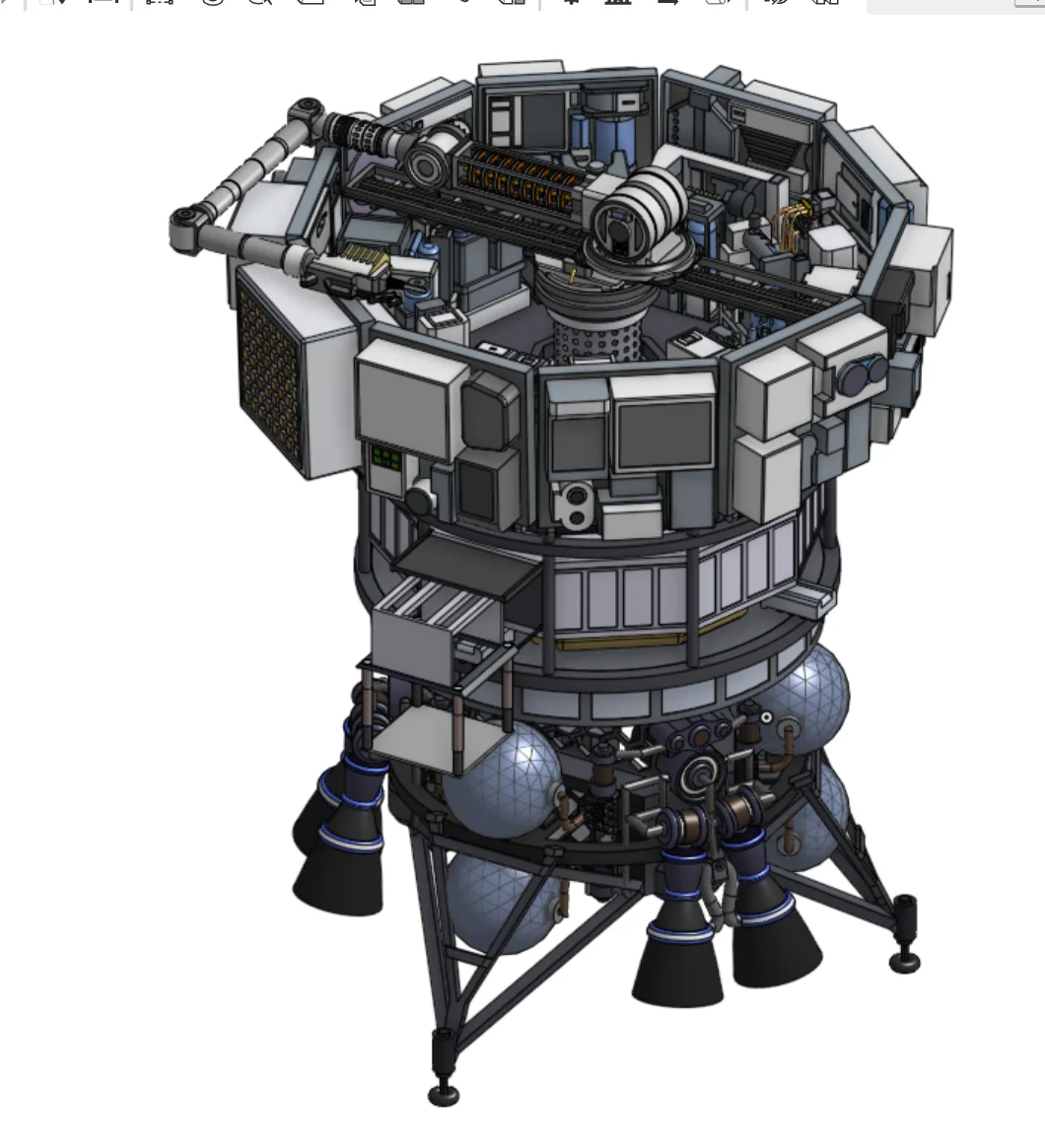
The robotic arm is the central mechanical component sitting at the very top of the upper module. Assemble this sub-assembly first before mounting it.
One. Base Foundation: Locate the main circular platform, which is the one featuring vertically mounted circular rings, and the railing piece. Secure the railing to the perimeter of this platform. This circular vertical mount serves as the pivot base that holds the entire arm.
Two. The Core Arm Segment: Take the central arm piece featuring the orange spiral detailing and secure its pivot point into the vertical ring mount on the base platform.
Three. Extension Linkages: Locate the extension piece consisting of a circle connected directly to a pole. Next, locate its counterpart, which is the similar-looking solid grey piece. Connect these pieces to the core segment, aligning them to form the continuous length of the arm.
Four. Arm Boom Extension: Take the series of grey cylinder pegs and link them together linearly to extend the reach of the arm outward from the main core.
Five. End Effector: Find the specialized component shaped like a lightbulb or sensor housing. Affix this firmly to the very end of the grey cylinder extension chain. Set the completed arm assembly aside.
Section Two: The Upper Module
This section forms the dense, panel-heavy upper crown of the vessel.
One. Panel Sorting: Gather the wide, low-profile perimeter panels. Note that each panel has a unique mechanical detail design on its face.
Two. Perimeter Construction: Lay the outer panels out in a circle, aligning them side-by-side.
Three. Interlocking: Bond the sides of the panels together sequentially to form a large, rigid outer ring. Set this crown aside temporarily while building the core support.
One. Panel Orientation: Gather the middle ring panels. These are distinct from the outer panels as they are narrower and oriented more vertically.
Two. Inner Ring Formation: Connect these vertical panels side-by-side to form a smaller, concentric inner circle.
Three. Middle Ring Plate: Position the circular middle ring plate horizontally. Mount the completed inner vertical panels directly on top of this plate, as it acts as the floor or structural shelf holding them upright.
Four. Bot Bay Integration: Take the Bot Bay frame, which is the internal skeletal support piece, and secure it directly beneath the middle ring plate.
Five. Storage Module: Attach the lower storage compartment component directly underneath the bot bay.
Section Three: The Descent Stage and Propulsion
This is the heavy structural foundation that sits directly on the ground.
One. Main Frame Placement: Place the large, heavy descent stage main frame flat on your workspace. This acts as the structural base for the entire model.
Two. Isosphere Tanks: Locate the multi-faceted isosphere propellant tanks. Because these parts are split during printing, first bond the halves together. Once dry, mount the completed spheres vertically into their designated slots inside the open framework of the main frame.
Three. Propulsion Plumbing and Engines: Locate the split fuel engine housings, bond the halves together, and mount them vertically onto the lower exterior structural beams of the main frame. Next, locate the split hexagonal nozzles. Assemble the nozzle halves, then affix them securely onto the bottoms of the fuel engine housings, pointing downward.
Section Four: Final Major Sub-Assembly Integration
Now, stack the completed modules together from the bottom up.
One. Lowering the Crown: Take the completed upper module assembly, which consists of the outer ring, middle ring, and bot bay stack, and lower it onto the upper mounting collar of the descent stage frame. Ensure it is centered and leveled.
Two. Installing the Mechanism: Take the completed robotic arm assembly from section one and drop its circular base platform directly into the top center opening of the middle ring.
ByChristianS_2237751Likes502Downloads3.7K

 ByRedfully_1701430Likes717Downloads3.3K

 ByDennisMLikes189Downloads1.7K

 ByJona32u4Likes82Downloads678

 Bymtakashi_164009Likes176Downloads491

 Bythall72Likes30Downloads522

 ByGhostmanta_3143708Likes187Downloads341

 ByHugoS_588209Likes108Downloads1.4K

 ByLimitSwitch_4355441Likes102Downloads291

 ByIngviMarLikes68Downloads798

 BytimquiLikes104Downloads150

 ByKevinM_876218Likes500Downloads617