


Mẫu gảy đàn Guitar (Guitar Pick) in 3D tùy chỉnh độ dày
 ByWolf_115355Likes513Downloads8.4K
Build another version of this model.
Part of the ExoGuitar project — full catalog, build planner, and assembly guides at https://exoguitar.com
Plan Your Build & Get Hardware
ExoGuitar can be confusing! Head over to our build planner to plan your entire build - it'll walk you through every available part and handle compatibility along the way, and it covers all ExoGuitar parts. It's also the best way to get hardware, since it lets you buy everything for a full build in one go, not just this part.
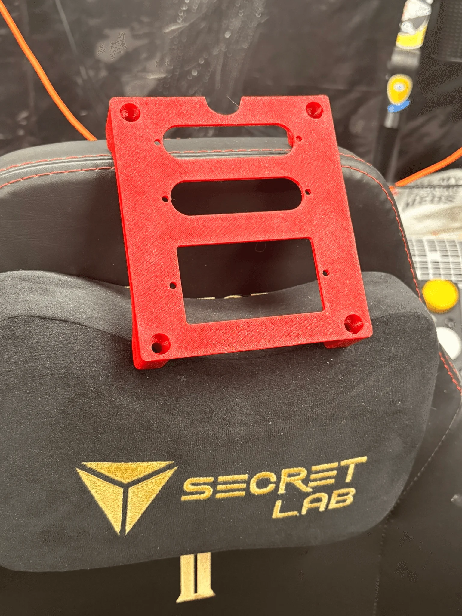
You can find this specific part, ExoGuitar - Face Plates - HSS, on our site.
The assembly process matches other printed electronic face plates: same printed hardware routing, pickups and switching vary by variant. Shared exploded illustrations may show Single Humbucker or another layout—the mechanical steps are the same pattern.
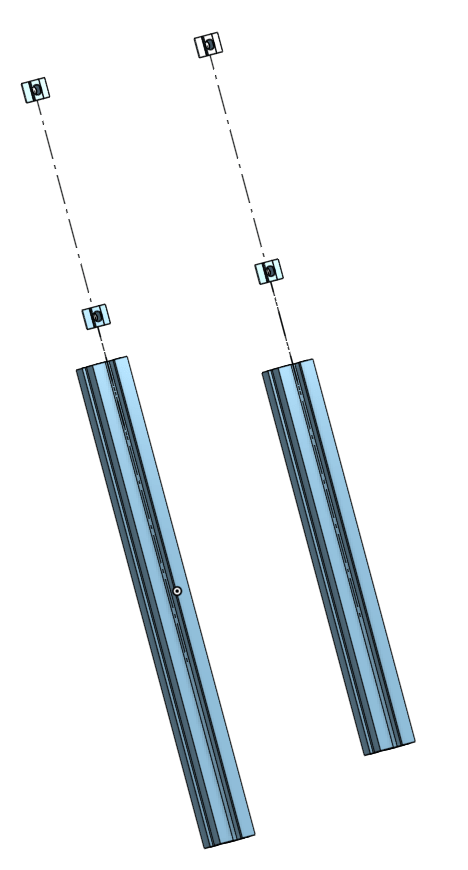
Step 1: Insert Slide In Nuts
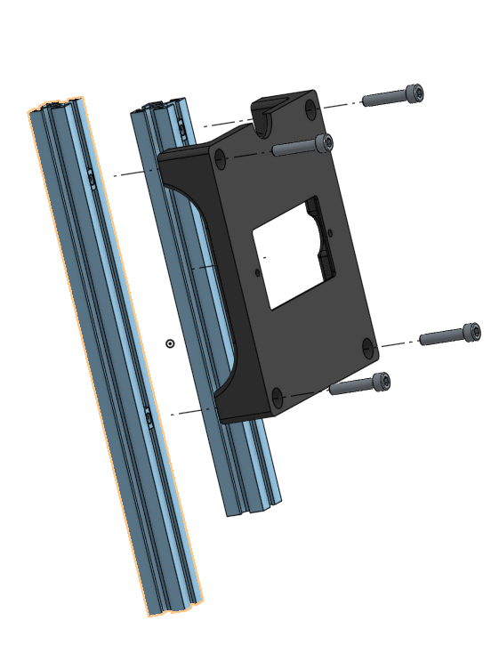
Step 2: Attach Faceplate to 2020
Step 3: Assemble Wiring Harness
Build the harness before you bury wires in the wing run. A disconnect between plate-side wiring and the longer loom into the wings avoids cutting solder when separating wings later.
Step 3a: Route Signals and Grounds
Rough-route Wire - 24 Gauge between pickups, switch, pots and output jack pads so bends clear printed clips and aluminium channels. Tie volume/tone/filter network per schematic for this face plate.
Step 3b: Optional JST Disconnect (Plate ↔ Wing Harness)
BOM Connector - JST 2 - Prewired rows are Optional — alternatively extend a single soldered loom.
(Optional) Fit one male + female 2-pin prewired JST pair per pickup listed on the BOM (three on Strat/HSS layouts, two on dual-pickup plates, one on single-humbucker plates) at the boundary between the face-plate harness and wires that disappear into extrusion channels / wing ducts. Trim to length only after polarity is marked; tug-test before heat-shrink.
Prefer traditional soldered joints everywhere → skip optional connector purchase.
Step 3c: Optional Spade Lugs at Pots/Switch/Jack
BOM Connector - Spade - 4.8mm is Optional.
(Optional) Slide insulated spade lug tails onto pot tags, switched commons or jack studs that accept tabs—avoids soldering heat repeatedly at cramped hardware. Match quantities to the BOM line for this plate (lug budget for pots, selector switch if listed on the BOM, and output jack).
Prefer tinning lugs directly with solder → omit connector line and solder as usual (equally fine).
Step 3d: Recommended Tooling — Crimps + Strips
For JST pigtails and insulated spade lugs, use a ratcheting crimp/strip tool listed under Recommended tools on the planner summary (tools.json at the catalog root—not a line item on this part BOM).
Verify continuity on every mating pair before snapping prints tight.
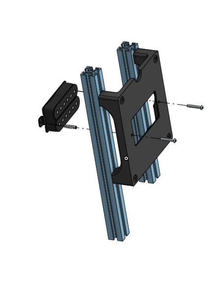
Step 4: Attach Electronics
Hardware
DIY Kit
You can order a DIY kit for your entire build from our build planner, the estimate for this part's kit is $107.39 plus shipping.
Self Source
If you want to order the parts yourself, here's a list. Estimated cost: $142.82.
ByWolf_115355Likes513Downloads8.4K

 ByspikeonLikes2Downloads10

 ByBasementLABLikes888Downloads1.5K

 ByZED4EverLikes313Downloads5.2K

 ByfifindrLikes500Downloads4K

 ByVC_DesignLikes679Downloads3.6K

 ByDan Schwartz SchwartzLikes744Downloads3.4K

 ByUpcrid3D_1585693Likes808Downloads2.1K

 ByWilko_SLOLikes935Downloads2K

 Bychubbs8697_2027893Likes585Downloads1.7K

 Byquibeck_3353173Likes965Downloads1.9K

 BySeppoTakaloLikes960Downloads1.9K