



Mô hình đường ray thẳng Lego City Train tự in 3D cực tiện lợi
 ByChristianS_2237751Likes502Downloads3.7K
Build another version of this model.
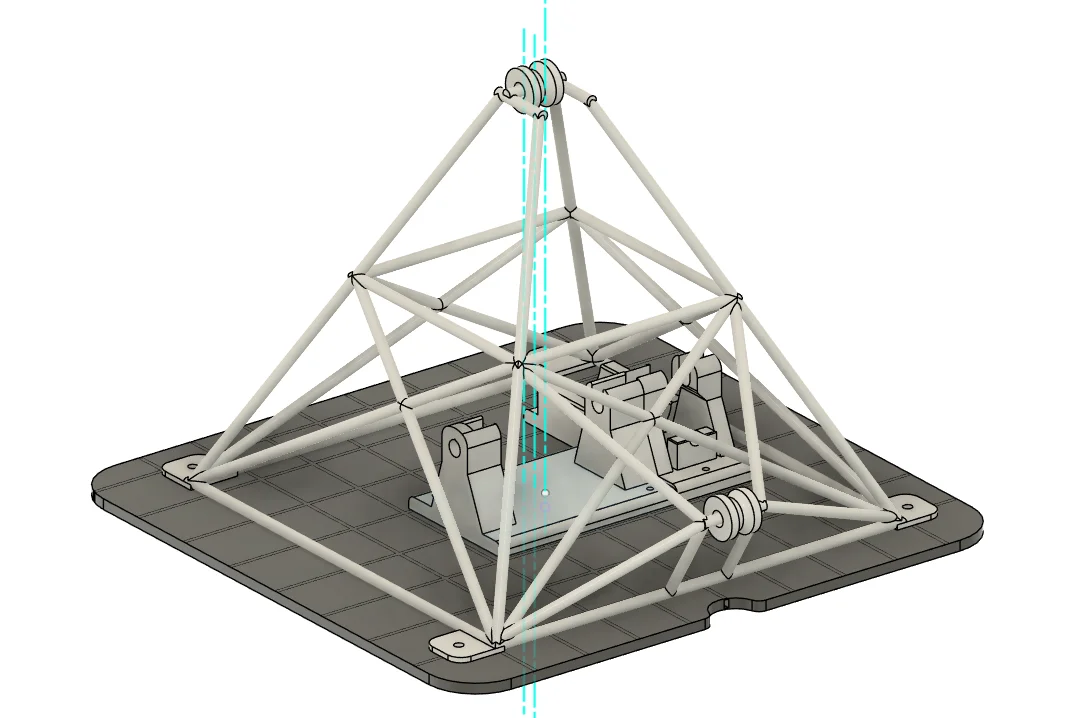
Tomé inspiración del archivo original (https://www.thingiverse.com/thing:3921644) para crear la estructura para un proyecto de la Universidad a la cual sólo tomé el final, no la pieza completa, para reimaginarlo como si fuera una especie de pozo minero (Mine headframe). Al igual que el original, las poleas giran libremente y están pensadas para ser impresas junto con la pieza.
Le agregué una base y unos soportes para un mecanismo que permite motorizar el artefacto. Para unir la base con el resto de la estructura recomiendo usar heat inserts de M3 y tornillos M3 también. Para unir los soportes con la base no son necesarios los heat inserts, puede ser con los M3 directamente.
El mecanismo es un tornillo sin fin unido a un engranaje con una relación de transmisión 1:14, para ser usado con un JGA25-370 12v DC Gear Motor 620 RPM (reduction rate: 9.6).
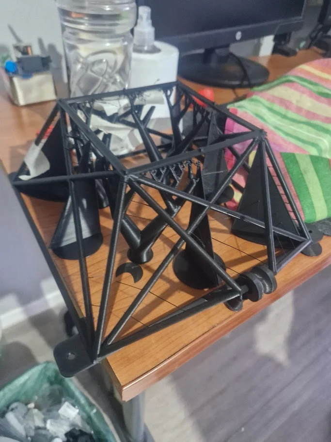
Agregué una versión de la estructura del pozo más fácil de imprimir para impresoras con mucho bed sliding como la mía (una CR-10S Pro V2), igualmente recomiendo usar soportes para las poleas y para los puentes intermedios, a menos que su impresora sea muy buena imprimiendo ese tipo de elementos sin soportes.
Se me perdieron las fotografías que tomé y tuve que entregar la maqueta a mi profesor, pero fue capaz de levantar 1 kg sin problema, utilizando una cuerda de lienza de maestro.
I took inspiration from the original file (https://www.thingiverse.com/thing:3921644) to create a structure for a university project. I only used the end section of the original model, rather than the entire part, and reimagined it as a type of mine headframe. As in the original design, the pulleys rotate freely and are intended to be printed in place together with the structure.
I added a base and mounting brackets for a mechanism that allows the assembly to be motorized. To attach the base to the main structure, I recommend using M3 heat-set inserts and M3 screws. Heat-set inserts are not required to attach the mounting brackets to the base, as the M3 screws can be installed directly.
The mechanism consists of a worm screw connected to a gear, with a 14:1 gear ratio. It was designed to be used with a JGA25-370 12 V DC geared motor rated at 620 RPM, with a 9.6:1 reduction ratio.
I also included a version of the mine headframe that is easier to print on bed-slinger printers like mine, a CR-10S Pro V2. I still recommend using supports beneath the pulleys and the intermediate crossbars, unless your printer is particularly good at printing these types of features without support material.
Unfortunately, I lost the photographs I had taken and had to submit the model to my professor. However, the mechanism was able to lift 1 kg without any problems, using mason’s line as the lifting rope.
ByChristianS_2237751Likes502Downloads3.7K

 ByRedfully_1701430Likes717Downloads3.3K

 ByDennisMLikes189Downloads1.7K

 ByJona32u4Likes82Downloads678

 Bythall72Likes30Downloads522

 Bymtakashi_164009Likes176Downloads489

 ByGhostmanta_3143708Likes187Downloads340

 ByHugoS_588209Likes108Downloads1.4K

 ByLimitSwitch_4355441Likes102Downloads291

 ByIngviMarLikes68Downloads797

 BytimquiLikes104Downloads149

 ByKevinM_876218Likes500Downloads616