



Bộ sưu tập 11 nhân vật mô hình Mecca Chameleon in 3D vui nhộn
 ByZED4EverLikes313Downloads5.2K
Build another version of this model.
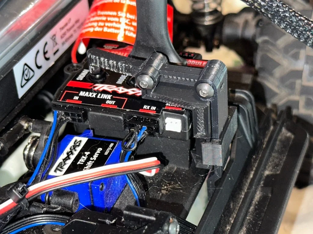
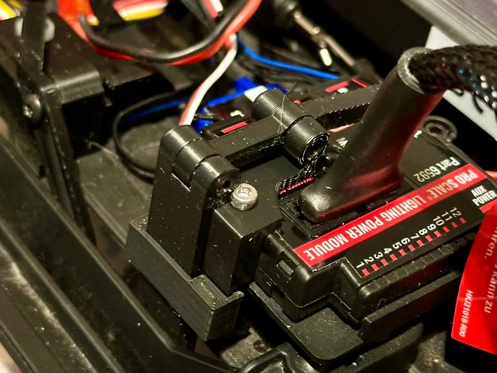
The Traxxas Pro Scale lighting system and iLink lighting control system are pretty slick, but the one thing you cannot do from the iLink app is turn the emergency flashers on and off: you have to remove the body and press a button on the controller. I took inspiration from the 3D-printed ESC power external switch pushers for the TRX-4 crawler and created a switch pusher for the Signal button on the Pro Scale lighting controller. It coexists nicely with the button pusher for the Hobbywing Fusion Pro motor/ESC combo (https://www.thingiverse.com/thing:4857941) and presumably the button pusher for the stock ESC (https://www.thingiverse.com/thing:3462473).
Here it is in action: https://youtu.be/myJxaxX0Shk
Printer Brand:
Snapmaker
Printer:
Snapmaker 2 A350
Rafts:
No
Supports:
Yes
Resolution:
0.2mm layers
Infill:
20%
Filament: Elegoo Rapid PLA+ Black
Notes:
This was actually printed on a Snapmaker Artisan
Post-Printing =============
In addition to the four 3D-printed parts, three machine screws are required: two M3x12mm (preferably button head) and one M2.5x25mm screw (cap head or button head).
The two M3 screws are the pins for the handle-to-lever hinge and the bracket-to-lever hinge and should be screwed into the side of the hinge opposite the Pro Scale breakaway connector.
The M2.5 screw replaces the outer Pro Scale lighting controller mounting screw (it's longer than the stock screw). There's a hole in the bracket that the screw goes through after exiting the plastic "nut" on the underside of the controller mount plate to stabilize the bracket. It can be a little tricky to get the screw to go through that hole.
The handle clip is optional. It mainly just takes the wobble out of the handle.
The assembly order is:

Category: R/C Vehicles
ByZED4EverLikes313Downloads5.2K

 ByprofessorbootsLikes0Downloads290

 ByleonicLikes0Downloads1.4K

 ByfifindrLikes500Downloads4K

 BymoonyxLikes0Downloads701

 ByVC_DesignLikes679Downloads3.6K

 ByDan Schwartz SchwartzLikes744Downloads3.4K

 Byvc-designLikes0Downloads3.2K

 Bythorin-oakenshieldLikes0Downloads536

 Bytorii-creative-studioLikes0Downloads454

 ByUpcrid3D_1585693Likes808Downloads2.1K

 ByshoheiyLikes0Downloads437