



Giá treo tai nghe Moai
 BykukulinLikes77Downloads515
Build another version of this model.
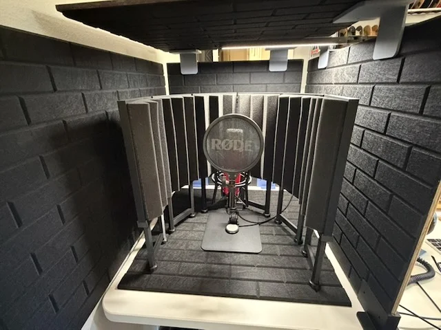
I needed a microphone isolation shield to help control reverb and external noise when recording voice overs. None of the available solutions were large or flexible enough for my application. I also wanted a system that I could reconfigure (add or subtract) should the need arise in the future.
I designed these to fit a 1/2 panel of 12" x 12" x 2" foam that you can typically buy on Amazon or FB Marketplace. You might also need to trim the height just a tad. I prefer the foam panel without the self adhesive because the aggressiveness and durability of the adhesive can vary from manufacturer to manufacturer. I used 3M's All Purpose Spray Adhesive. You can spray just one side in case you may want to replace the panels in the future, or both sides for a more permanent bond. I also designed these for a table top placement.
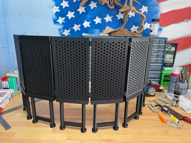
Since thess are on the larger side, it definitely needs a printer with at least 300mm in one of the dimensions. There is a left panel, a right panel, and an inside panel. The left and right are for the ends and print as many inside panels that you might need for your application (I needed a total of 6 panels). I've also included 3 different base heights to choose from. (I needed the tall one.) Print the panels and the bases separately and glue them together when done.
The way that I assembled them: 1) Print the panel and bases 2) Glue the panel and bases together 3) Attach the foam to the panels, trimmed to fit 4) Pin the panels together - don't glue.
Tips: 1) I added modifiers to the hinges with 100% infill for reenforcement. 2) Print the connector pins also @ 100% infill. If your printer prints the pins a little too large, sand them gently to fit, but it should be a snug fit. 3) To help with assembling the panels together, I aligned the hinges 90º to each other for easier access and to get the pins to slide in easier. If there were any pins that needed a little '"persuasion", I used a punch and GENTLY tapped them into place with a tack hammer. Just make sure the hinges are in line with each other before tapping them in.
My settings:
Typical PLA filament settings
.2 height
2 walls, 25% infill-perimeter overlap
15% gyroid infill global setting
Pins were printed upside-down w/ 5mm brim
Panels don't need supports or brim (when printed on back), hinges printed @ 100% infill w/ modifiers
Bases - Organic (manual) supports
I hope you find these useful and effective for your application, and happy printing and recording!
BykukulinLikes77Downloads515

 ByckthLikes148Downloads2.4K

 ByTimSomeCallMeLikes35Downloads240

 ByFredRaket_1274632Likes60Downloads280

 ByOwenWalker_2453164Likes3Downloads53

 ByKastnerd_192794Likes21Downloads228

 ByJaronLikes310Downloads1K

 Byw3rN42Likes127Downloads931

 ByTurbosol_2577940Likes53Downloads89

 ByTomDDLikes89Downloads574

 ByrpservisLikes10Downloads67

 Byparts-expressLikes0Downloads104