



Core One (L) Devil's Horns
 BythomersLikes0Downloads113
Build another version of this model.
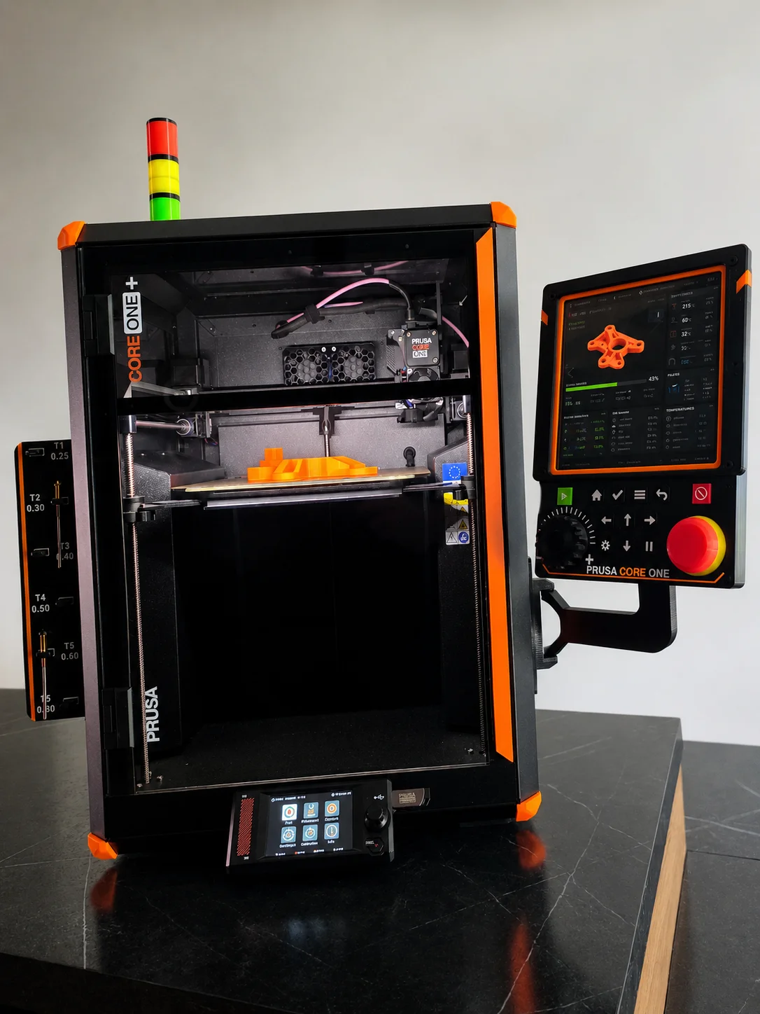
Turn your Prusa CORE One into a small industrial-style CNC operator cell.
This project is a complete visual skin kit inspired by CNC machine control stations. It adds an external operator panel, side arm, nozzle tool rack, status light and corner guards while keeping the printer fully usable.
The idea was to create something that looks like a real machine upgrade, not just a decoration — but still make it easy to print, assemble and customize.
What is included
The kit includes:
CNC-style operator panel
movable side arm and printer mount
nozzle tool rack / tool library
decorative status light
corner guards
printable HMI screen graphic
optional print-only panel body
test-fit button parts
optional arm mount alignment tool
prepared 3MF print plates
Main features
Designed specifically for Prusa CORE One
Support-free printing — no supports required
Parts are split by color and function
Prepared STL and 3MF files included
Manual filament changes can be used for raised icons and text
Operator panel can be built with or without acrylic
Does not block the door, controls, ventilation or print volume
No electronics required
Non-permanent installation
Designed from scratch in CAD
Operator panel
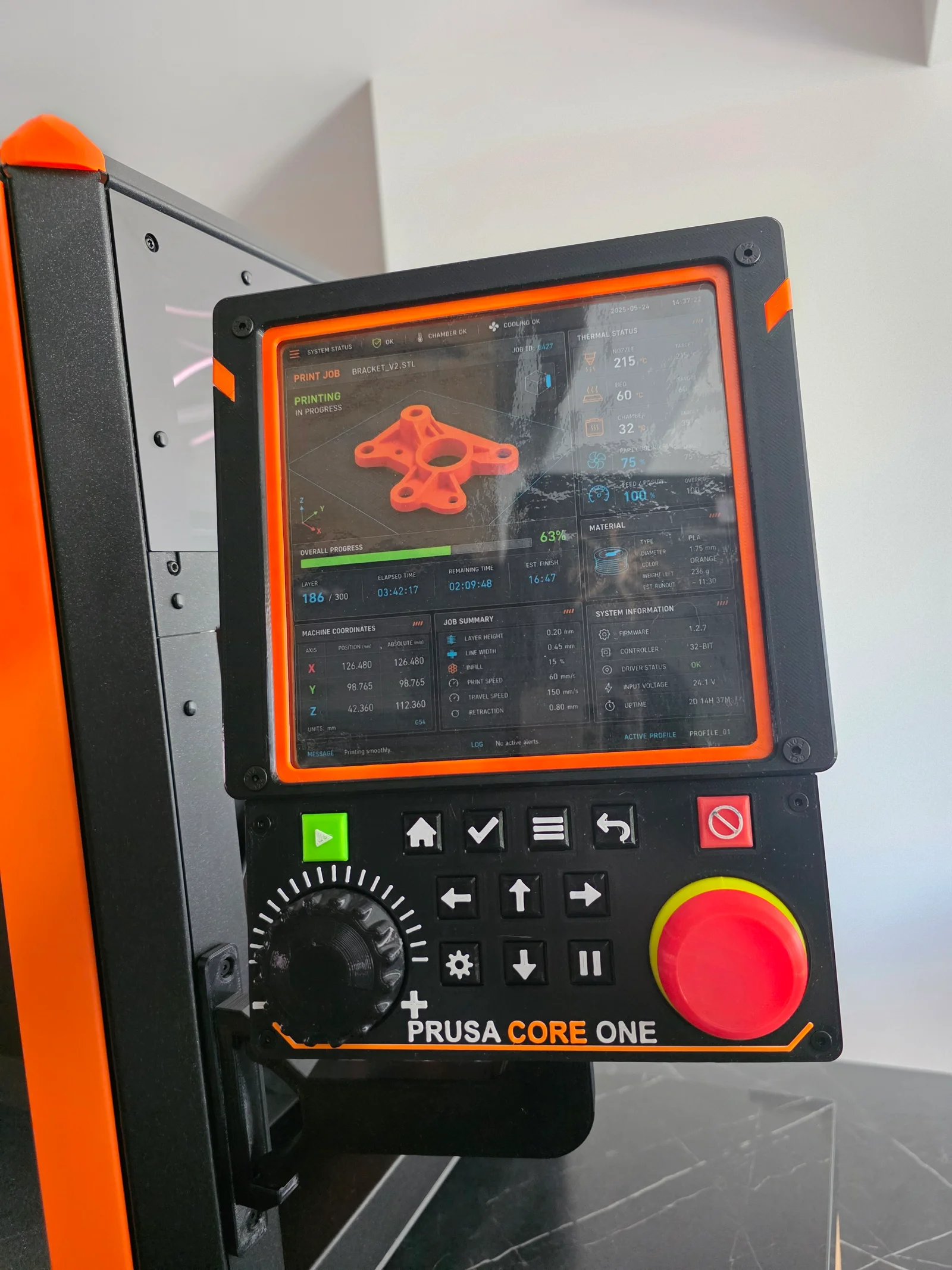
The operator panel is the main part of the kit. It is a CNC-inspired pendant with a printed HMI screen, physical-looking buttons, jog wheel and decorative E-stop.
Two panel body versions are included:
Recommended version.
Uses a printed HMI graphic under a clear acrylic / plexiglass sheet:
This gives the screen a more realistic industrial HMI look.
For users who do not have acrylic.
This version has a shallow 0.15 mm recess for the printed HMI graphic / sticker. The rest of the panel assembly stays the same.
HMI graphic
A printable HMI screen graphic is included.
Print it at 100% scale.
Use the included A4 print sheet with crop marks and the 100 mm scale check line.
Important print settings:
Print at 100%
Use Actual Size
Disable Fit to Page / Scale to Fit
Check the 100 mm scale line after printing
Nozzle tool rack
The side tool rack is inspired by a CNC tool library.
It is labeled as a nozzle library:
T1 — 0.25
T2 — 0.30
T3 — 0.40
T4 — 0.50
T5 — 0.60
T6 — 0.80
It adds a practical and visual “tool magazine” detail to the printer.
Status light
The status light is decorative and does not require electronics.
It is printed as one part and can be made with manual filament changes.
In this build, the status light is mounted using double-sided tape.
Corner guards
The corner guards are small orange accent parts that complete the industrial machine look.
They can be mounted in two ways:
with double-sided tape
with magnets embedded during printing
If you want to use magnets, add a pause in the slicer at the magnet pocket height, insert the magnets, and then continue the print.
If you do not want to use magnets, print them normally and mount them with double-sided tape.
Printing notes
All parts are designed to print without supports.
Suggested colors:
Black / dark graphite — main parts
Orange — Prusa-style accents
White — raised icons and text
Red + yellow — E-stop
Green / yellow / red / black — status light
Manual filament changes
Some parts are designed for manual filament changes on a single-material printer.
This applies especially to:
button icons
lower faceplate text
status light color sections
nozzle tool rack labels
Print the base color first, then pause and change filament for the raised text or icon layers.
Prepared 3MF files are included to make this easier.
Hardware and additional parts
You may need:
150 × 150 × 3 mm acrylic / plexiglass sheet
M3 heat-set inserts
M4 heat-set inserts
M3 screws
M4 screws
nuts for the printer-side mounts
double-sided tape
optional magnets for corner guards
Heat-set inserts for the operator panel
The file CORE_One_CNC_panel_body.stl uses 12 heat-set brass inserts in total.
Front side:
4 × M4 heat-set inserts
Hole diameter: Ø6 mm
Hole depth: 6.2 mm
4 × M3 heat-set inserts
Hole diameter: Ø5 mm
Hole depth: 8.2 mm
Rear side:
Suggested screw length rule:
screw length = insert hole depth + approx. 2 mm
Typical screw ranges:
M3 screws: M3x10–M3x12
M4 screws: M4x8–M4x10
Exact screw length may depend on the inserts and screws you use.
Test-fit parts
Button test-fit parts are included:
CORE_One_CNC_panel_test_fit_button_socket.stl
CORE_One_CNC_panel_test_fit_button.stl
The test-fit button currently has 0.2 mm clearance on the length.
Print these first if you want to check your printer tolerance before printing the full operator panel. If the fit is too tight or too loose, adjust XY compensation / horizontal expansion in your slicer.
Optional alignment tool
An optional alignment tool is included:
CORE_One_CNC_arm_mount_alignment_tool.stlIt helps hold the nut in position from inside the printer while tightening the mount screw from the outside.
This tool is only used during assembly and is not part of the final installed kit.
Important installation notes
The printer-side mounts use screws from the outside and nuts from the inside of the printer. This keeps tool access on the outside and makes installation easier.
Important:
The screw must not protrude more than 9 mm inside the printer.
If the screw sticks out more than 9 mm inside the printer, the Z-axis bed mount may collide with it during movement.
After installation, always check that:
the door opens correctly
the bed can move freely
ventilation is not blocked
the print volume is not affected
all parts are mounted securely
Disclaimer
This is a decorative / visual CNC-style skin kit.
It does not modify the printer electronics and the operator panel controls are decorative.
Always check clearances after installation before running the printer.
Start with CORE_One_CNC_panel_body.stl.
This is the main body of the operator panel.
Make sure the inserts are seated straight and flush with the surface.
Turn the panel body over and install the rear heat-set inserts.
These inserts are used for mounting the panel to the arm.
Press the two orange side accent pieces into the side slots of the panel body.
Files:
CORE_One_CNC_panel_side_accent_left.stl
CORE_One_CNC_panel_side_accent_right.stl
They are decorative accent parts and should sit flush with the front frame.
If you printed the test-fit parts and everything was correct, it should fit. If not, you can use glue.
The buttons, jog wheel and E-stop are decorative elements and do not connect to the printer electronics.
Press the red E-stop button into the yellow E-stop ring.
File:
CORE_One_CNC_panel_estop_button.stlIf you printed the test-fit parts and everything was correct, it should fit. If not, you can use glue.
Prepare the screen frame parts:
CORE_One_CNC_panel_screen_insert_orange.stl
CORE_One_CNC_panel_screen_frame.stl
The orange screen insert sits around the visible HMI graphic.
The black screen frame holds the acrylic / plexi sheet mechanically from the front.
Place the printed HMI graphic into the screen pocket.
For the acrylic version, place a clear acrylic / plexiglass sheet on top of the graphic:
Print the HMI graphic at 100% scale. Disable “fit to page” or “scale to fit” when printing.
Place the black screen frame over the display area and secure it with screws.
File:
CORE_One_CNC_panel_screen_frame.stlPrepare the lower faceplate.
File:
CORE_One_CNC_panel_lower_faceplate.stlThe raised text and details can be printed using manual filament changes - just use 3mf file.
Attach the lower faceplate to the front of the operator panel and secure it with screws.
Prepare the printed arm part.
File:
CORE_One_CNC_arm_panel_mount.stlPlace the arm on the rear side of the assembled operator panel and secure it using screws.
Use the rear M4 heat-set inserts installed earlier in the panel body.
Make sure the arm is aligned correctly before tightening the screws.
Do not overtighten the screws. The arm should sit flat against the back of the panel and hold the panel firmly.
The operator panel is now ready to be installed on the printer-side mount.
Prepare the nozzle tool rack parts.
Files:
CORE_One_CNC_tool_rack_nozzle_holder.stl
CORE_One_CNC_tool_rack_orange_strip.stl
The nozzle holder is labeled as a small CNC-style tool library:
T1 — 0.25
T2 — 0.30
T3 — 0.40
T4 — 0.50
T5 — 0.60
T6 — 0.80
The raised labels can be printed using manual filament changes.
Press or slide the orange accent strip into the side channel of the nozzle tool rack.
Before installing the mounts, move the print bed all the way up.
This gives you more space and better access to the inside of the printer during installation.
Remove the four factory plastic rivets from the printer side panels.
There are four rivets in total:
2 rivets on the right side
2 rivets on the left side
Use the first photo to show the rivet locations with arrows.
Use the second photo to show the mounting points after the rivets have been removed.
The rivets can be gently lifted with a thin flat tool or small screwdriver and should come out without much force.
Be careful not to scratch the printer frame or side panels.
Repeat the same operation on the opposite side of the printer.
Keep the rivets in case you ever want to return the printer to its original state.
Install the two printer-side mounts using screws from the outside and nuts from the inside of the printer.
Files:
CORE_One_CNC_arm_printer_mount.stl
CORE_One_CNC_tool_rack_mount.stl
To make installation easier, use the optional printed alignment tool.
File:
CORE_One_CNC_arm_mount_alignment_tool.stlPress the nut into the alignment tool and hold it against the inside of the printer
Mounting sequence:
Place the printed mount on the outside of the printer.
Insert the screw from the outside through the mount and into the printer frame.
Hold the screw from the outside with an Allen key or screwdriver
From the inside of the printer, place the nut and alignment tool onto the protruding screw.
Turn the screw from the outside until it catches the nut.5
Tighten the screw carefully while keeping the nut aligned with the tool.
This keeps tool access on the outside of the printer, which makes installation much easier.
Important clearance note:
The screw must not protrude more than 9 mm inside the printer.
If the screw sticks out more than 9 mm inside the printer, the Z-axis bed mount may collide with it during movement.
Before continuing, manually check that there is enough clearance between the screw end and the Z-axis bed mounting parts.
Repeat the same mounting process on the opposite side of the printer for the nozzle tool rack mount.
Install the assembled operator panel with the arm onto the printer-side arm mount.
Start by placing the lower part of the arm onto the printer mount first.
Then slide the upper part of the arm in from the side, using the chamfered area as the entry point.
Make sure the arm moves into position smoothly and does not force the mount sideways.
The arm is now installed and can be moved into the desired operator panel position.
Take the previously assembled nozzle tool rack and install it onto the tool rack mount on the opposite side of the printer.
Install the printed corner guards on the printer corners.
Files:
CORE_One_CNC_corner_guard_magnet_ready.stlThe corner guards can be mounted in two ways:
with double-sided tape
with magnets embedded during printing
If you want to use magnets, print the magnet-ready version and add a pause in the slicer at the magnet pocket height. Insert the magnets during the pause, then continue the print. The magnets will be embedded inside the corner guard.
If you do not want to use magnets, simply print the corner guards normally and mount them with double-sided tape.
Mounting sequence:
Clean the printer corner surface.
If using magnets, make sure they were embedded during printing.
If using tape, apply double-sided tape to the inside of the corner guard.
Align the corner guard with the printer corner.
Press it gently into place.
Install the printed status light on top of the printer.
File:
CORE_One_CNC_status_light.stlIn this build, the status light is mounted using double-sided tape.
Mounting sequence:
Clean the top surface of the printer.
Apply double-sided tape to the bottom of the status light.
Place the status light on top of the printer.
Press it gently into place.
Make sure it does not block ventilation openings.
The CNC Operator Skin is now installed on the Prusa CORE One.
Before using the printer, check that the door opens correctly, the bed can move freely, ventilation is not blocked, and all mounted parts are secure.
BythomersLikes0Downloads113

 ByBrokentooth_designsLikes23Downloads409

 Bytinx_1344834Likes1.2KDownloads6K

 Bybloblis67Likes0Downloads318

 By3DSourcererLikes48Downloads377

 Bymateusz-tokarzLikes0Downloads165

 Bydominik-chuchlikLikes0Downloads120

 Byprusa-researchLikes0Downloads2.7K

 BydjcodyLikes1Downloads11

 ByBretDorssers_4183352Likes19Downloads53

 ByKRYS_3DLikes8Downloads45

 Bypeter-van-der-waalLikes0Downloads255