

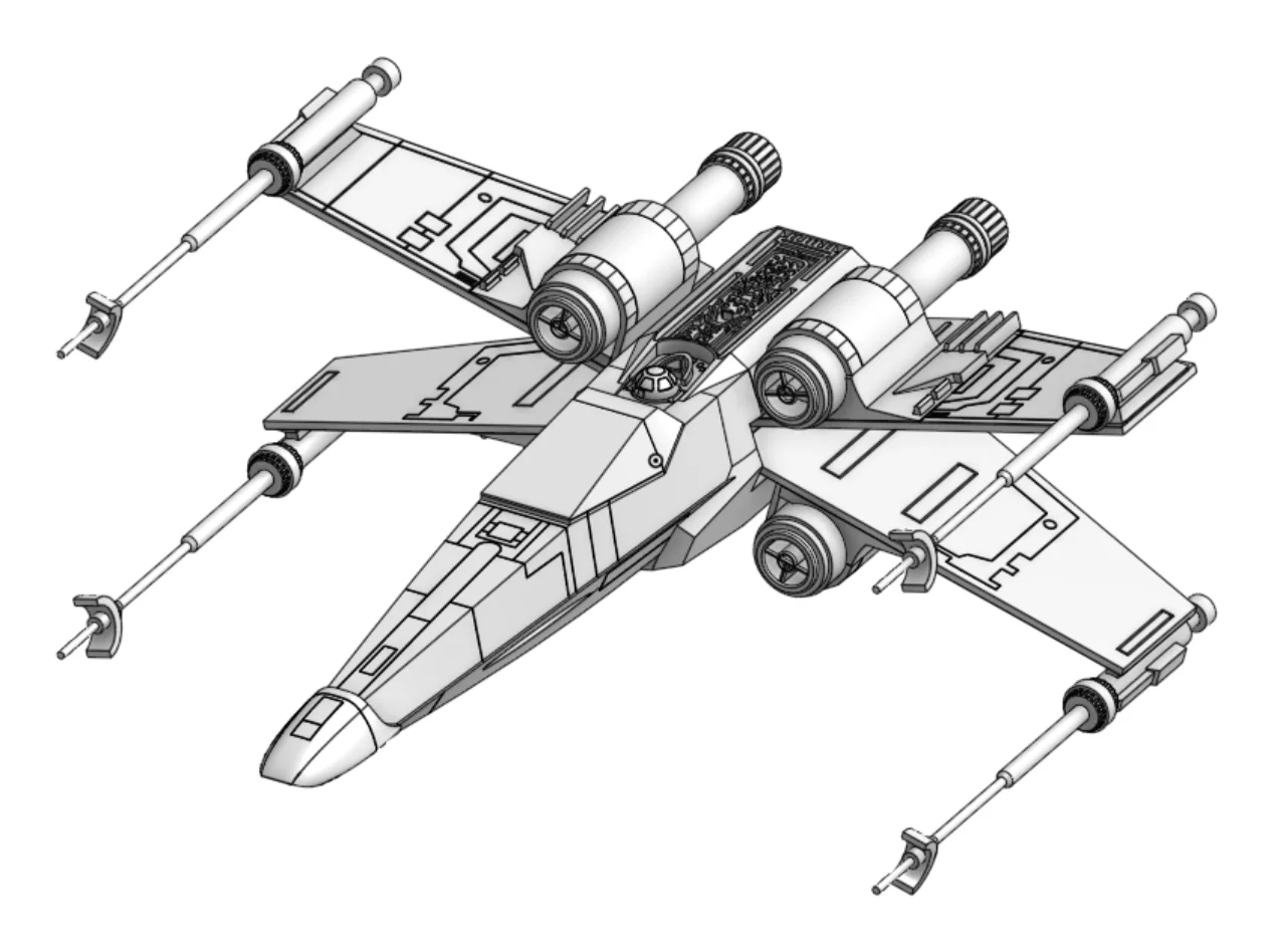


Kẹp giữ sợi Filament
 Bytinx_1344834Likes1.2KDownloads6K
Build another version of this model.
Phase 1: Post Processing and Dry Fitting
• Use flush cutters and a hobby knife to remove all support material and brims. Focus on the inner tracks of the outer engine housings and the alignment tabs on the cylindrical cores. • Perform a full dry fit by assembling the major parts without glue. FDM prints can expand slightly, so check how the inner engine cores slide into the outer housings. If the fit is tight, sand the contact areas with 220 grit until they move smoothly. • Wipe all mating surfaces with a microfiber cloth to remove dust so the adhesive bonds properly.
Phase 2: Assembly Sequence
• Apply a thin layer of CA glue or epoxy to the flat split faces of the nose cone and lower fuselage. Press them together for about thirty to sixty seconds. • Add glue to the vertical rear face of the fused nose section. • Press the yellow rear engine block into place and make sure the dome detail on top stays centered along the fuselage.
• Match each inner cylindrical core with its correct outer housing orientation. • Slide the core into the housing and confirm the raised alignment rails line up with the keyways. • Apply glue along the internal track or base plate and slide the core fully into position. Confirm the turbine ridges face forward. • Repeat for all engine pods.
• wing plates or hinge loops were printed in halves, so glue the flat backs together to form solid pieces. • Attach each engine pod to its guide slot on the wing plate. • Insert the wing tip cannons into their mounting holes and make sure they sit parallel to the wing edge before the glue sets. To assemble the blaster sub-assemblies, start by organizing your components into identical mirrored sets to avoid mixing up the upper and lower configurations. If the long barrel shafts or the main cylindrical bodies were split into halves to optimize printing, bond the flat backs together first with a thin layer of super glue or epoxy to form the complete, round pieces. Once the main barrel is fused, carefully slide any decorative rings, nozzle caps, or targeting greebles onto their designated positions along the shaft. Finally, attach the completed blaster barrel to its corresponding mounting block or wing bracket, ensuring it sits completely parallel and square before the adhesive sets completely.
• Attach the left and right wing assemblies to the fuselage using the alignment pins or slots. Confirm both wings sit perpendicular to the body. • Add any remaining small greebles, dials, or landing gear to their recessed areas.
Bytinx_1344834Likes1.2KDownloads6K

 Byprusa-researchLikes0Downloads2.7K

 Bypjs37Likes0Downloads155

 Bygafyx3dLikes0Downloads120

 Byduo3dprintLikes0Downloads152

 BylaserbaconLikes0Downloads171

 ByswimLikes0Downloads108

 Byarhi_585078Likes64Downloads540

 ByleopoldmozartLikes0Downloads135

 By3d-mmakerLikes0Downloads114

 Bynadir-cn3dLikes0Downloads110

 ByHanzo3dLikes155Downloads413