

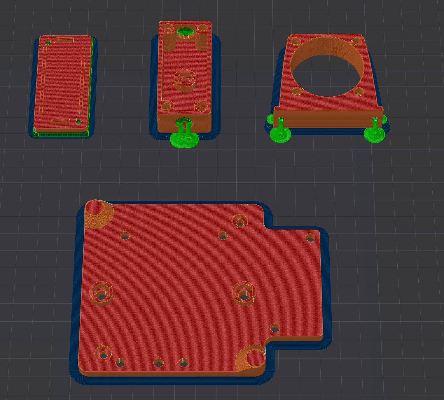
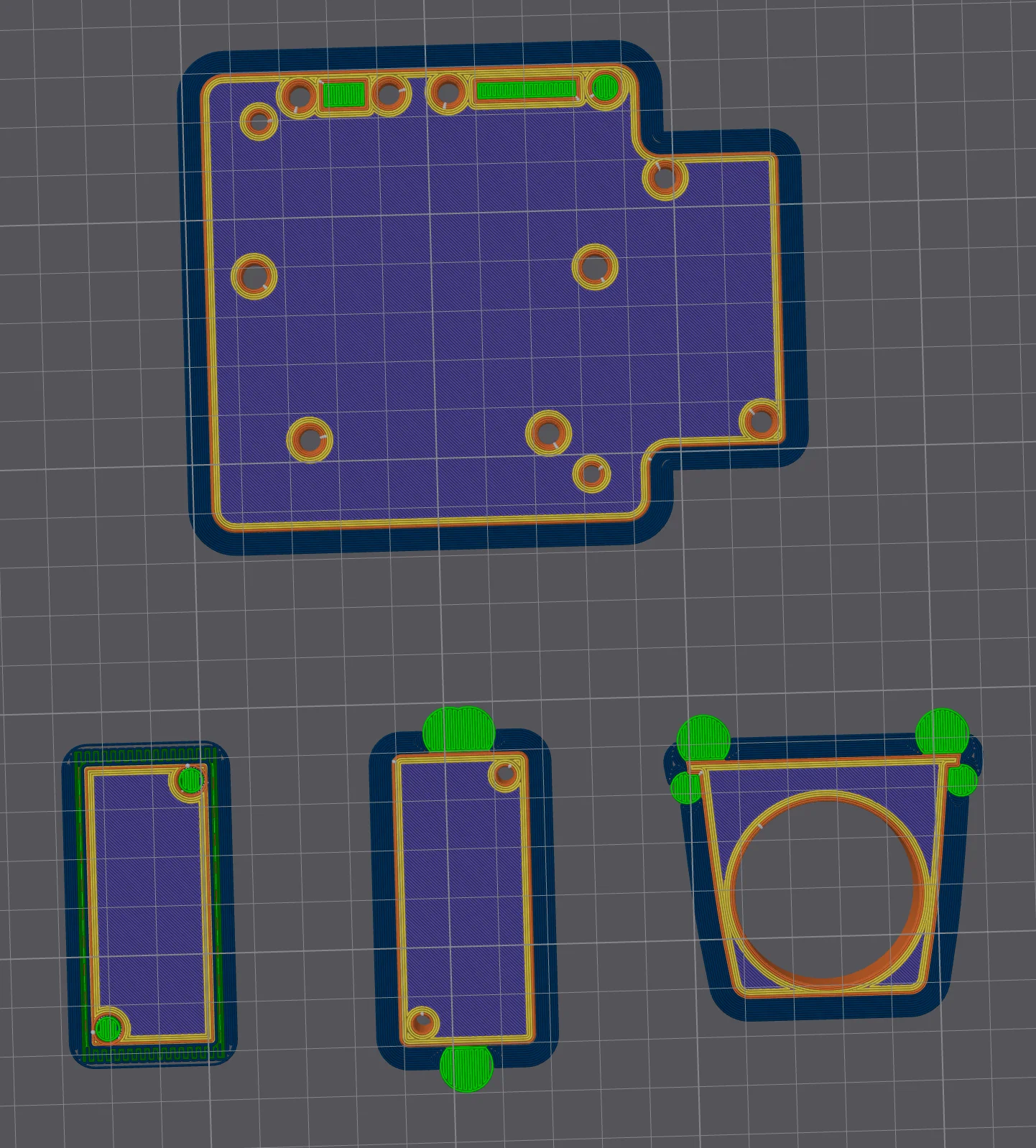


Kẹp giữ sợi Filament
 Bytinx_1344834Likes1.2KDownloads6K
Remix of Gá Lắp Modular SSR Cho Qidi Plus 4 (Modular SSR Mounting Bracket) By Sarge013
Build another version of this model.
Required materials:
14x M3-5-4 (voron spec) heat inserts
3x male JST-XH 20cm wires (note that the wire colors are reverse from normal)
1x 24v 4010 axial fan (can use stock mainboard fan)
1x M4x6mm SHCS
1x M4 hex nut
1x M4 flat washer
2x M5 hex nuts
2x M5 flat washers
2x M5x10mm SHCS
6x M3x6mm SHCS
2x M3x8mm SHCS
4x M3x15mm SHCS
2x M3x18mm SHCS
2x M3 flat washers
A soldering iron, wire cutters/crimper, solder, helping hands, and heat gun
With thermal switch option:
2x 2-slot Wago connectors
Press all inserts into the plate, junction box, and fan shroud. Press nuts into the junction box and mounting plate. Solder two male JST-Xh wires together and heatshrink the connection. Crimp two spade terminals to the third set of wires with opposite colored shrink to remind you of the reversed wiring, because getting the polarity wrong will damage the SSR. Mount the SSR to the heatsink. Mount the splicer and splitter in their respective slots. Mount the heatsink to the plate using the M5 screws and washers. Mount the fan shroud using the M3 screws and washers, and mount the fan to the fan shroud in the correct orientation to blow across the heatsink and with the wire oriented towards the upper right.
Make sure the printer is off and unplugged. Remove the back panel and then ground yourself. Remove the SSR cover, and the stock SSR, making sure to keep the AC in wires separate from the AC heater wires.
Take the two neutral AC wires, pass them through each of the holes in the junction box. Fix them firmly in place and contact with each other using the M4x screw and washer. Put the lid on the junction box and secure it in place with 2x M3x screws. Mount the junction box to the plate using 2x M3x screws. Attach the ground wire to the SSR heatsink CORRECT THIS. Attach the red heater AC wire to terminal 1 on the SSR.
OPTIONAL: cut the red AC in wire about X inches from the terminal ring. Strip both ends of the cut according to the markings on the Wagos. Twist the strands and insert each into a separate Wago connector. Trim the insulation and/or wire of the thermal switch according to the markings on the Wago and insert each end into the left over ports in the Wagos. Tuck the thermal switch into the heat sink so it is snug. Attach the red AC in wire to terminal 2.
Attach the SSR cooling fan wire to the center of the splitter. Attach the SSR cooling fan connector to the center of the splitter. Attach the chamber heater fan connector to the right splitter slot. Attach the XST-Xh jumper to the left splitter slot and the upper right fan connector on the mainboard. Attach the SSR control wire (white and white/blue) to the splitter, and attach the spade terminal connector to the splitter as well. Follow the positive and negative wires as indicated on the board, and connect the spade connectors to the correct input terminals on the SSR.
Attach the spade terminals to the correct input terminals on the SSR. Follow the positive and negative wires from the mainboard (marked on the board) to the splitter to the SSR to confirm.
Remember to use heat-resistant filaments that are not carbon fiber filled. PA6-GF formulas that do not require chamber heating are a good option if you are worried about the state of your OEM SSR. If you are not concerned, PPA-GF, PPS-GF, and PC-ABS-FR are all good options as well.
Build pictures and red AC wire cut length coming soon™.
Bytinx_1344834Likes1.2KDownloads6K

 Byprusa-researchLikes0Downloads2.7K

 Byarhi_585078Likes64Downloads542

 ByHanzo3dLikes155Downloads415

 BydarienLikes0Downloads1K

 Byds-printsLikes0Downloads352

 ByGeek5DLikes147Downloads485

 ByBrokentooth_designsLikes23Downloads409

 Byla-cave-au-chatLikes0Downloads967

 Bycrawler-3903250Likes0Downloads907

 Bytp98Likes0Downloads280

 ByvertigomakesLikes0Downloads563