


Còi Tàu Hơi Nước Mini
 ByfifindrLikes500Downloads4K
Build another version of this model.
NOT COMPLETE YET!
I am working on completing the set.
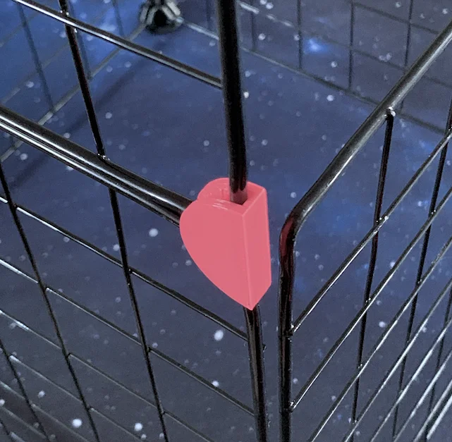
Important: Please note that these connectors are testet on a wire grid frame with a width of 4 mm.
The original part has a hight of roughly 20 mm and a width of 36 mm.
If you're missing variations, please just tell me.
You can contact me here or on Instagram: https://www.instagram.com/clouded.cat
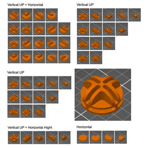
In order to address the different variants of the grid connectors, I will introduce a naming system.
The picture below shows the "biblically accurate" version of one huge, giant, monster-connector.
It is separated into two different planes: the horizontal and the vertical plane. Each plane is optional, so don't be alarmed when one or two of them are missing!
The horizontal plane has two separate instances: the up and the down part. It is divided into the cardinal directions North, East, South and West. If the connector uses both (the up and the down) planes, they will additionally be marked with up/down.
The vertical plane is divided into the regions North-East, North-West, South-East and South-West. For this one, there are no other variations.
Some connector variations only use the height of the horizontal plane. These will be addressed as +H.
I printed all of the connectors using PLA for fast prototyping. Keep in mind, that PETG, ABS or ASA would probably provide more stability and durability. The "real world" connectors I based this model on are made out of ABS.
For the horizontal plane prints, when you cannot avoid using support, I find that the organic support works best. Be careful, when removing the support: you can easily remove the grid lines as well.
If you're printing a model laying flat on the horizontal plane, you will run into some stability issues with the division lines of the notches. The walls are pretty thin, so handle with care.
I kept the walls this thin, because the original connector I based this model on, has this wall width. I wanted to make sure that you can continue using them.
26.05.2026
Rework of "vertical UP" and "horizontal" models with new / consistent names
Rework of "horizontal" plane, tried to increase stability by creating a curved wall
ByfifindrLikes500Downloads4K

 ByVC_DesignLikes679Downloads3.6K

 ByDan Schwartz SchwartzLikes744Downloads3.4K

 Bychubbs8697_2027893Likes585Downloads1.7K

 Byquibeck_3353173Likes965Downloads1.9K

 ByRungeKuttaLikes229Downloads1.2K

 ByEadubsLikes228Downloads1.3K

 ByJeremyVillalo_760366Likes68Downloads767

 ByZED4EverLikes313Downloads5.2K

 Bykjus_448782Likes314Downloads673

 BySchmitzBertLikes95Downloads629

 ByNathanKun_342409Likes132Downloads590