



Bộ sưu tập 11 nhân vật mô hình Mecca Chameleon in 3D vui nhộn
 ByZED4EverLikes313Downloads5.2K
Build another version of this model.
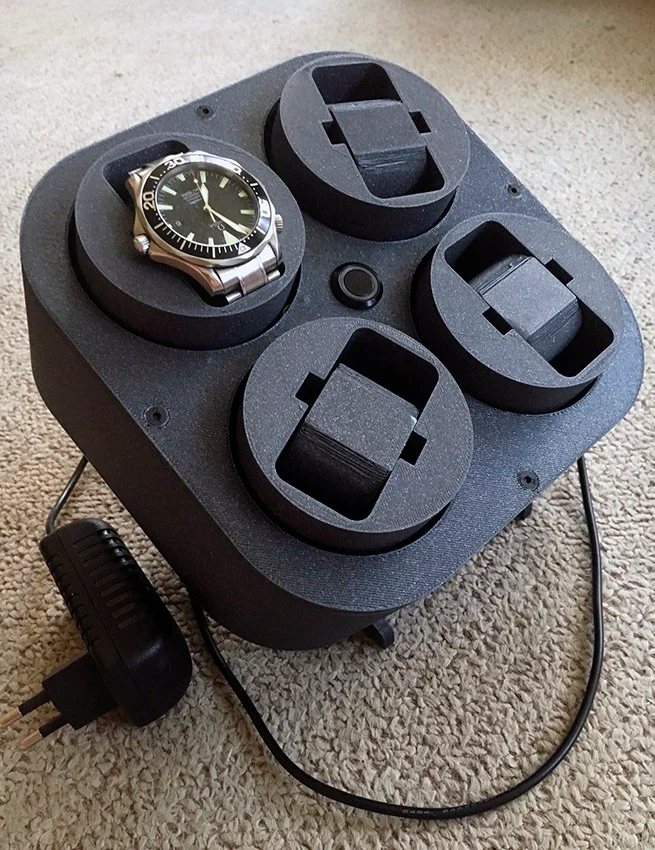
This watch winder is inspired by this thing: https://www.thingiverse.com/thing:2021221
Thank you Simone Dassi!
I adopted the shape of watch holder and plug. I modelled all parts in Fusion 360 from scratch.
ATMEGA is programmed like "Arduino on breadboard" as seen here:
https://www.arduino.cc/en/Tutorial/ArduinoToBreadboard - the minimal version without external clock, running on 8 MHz.
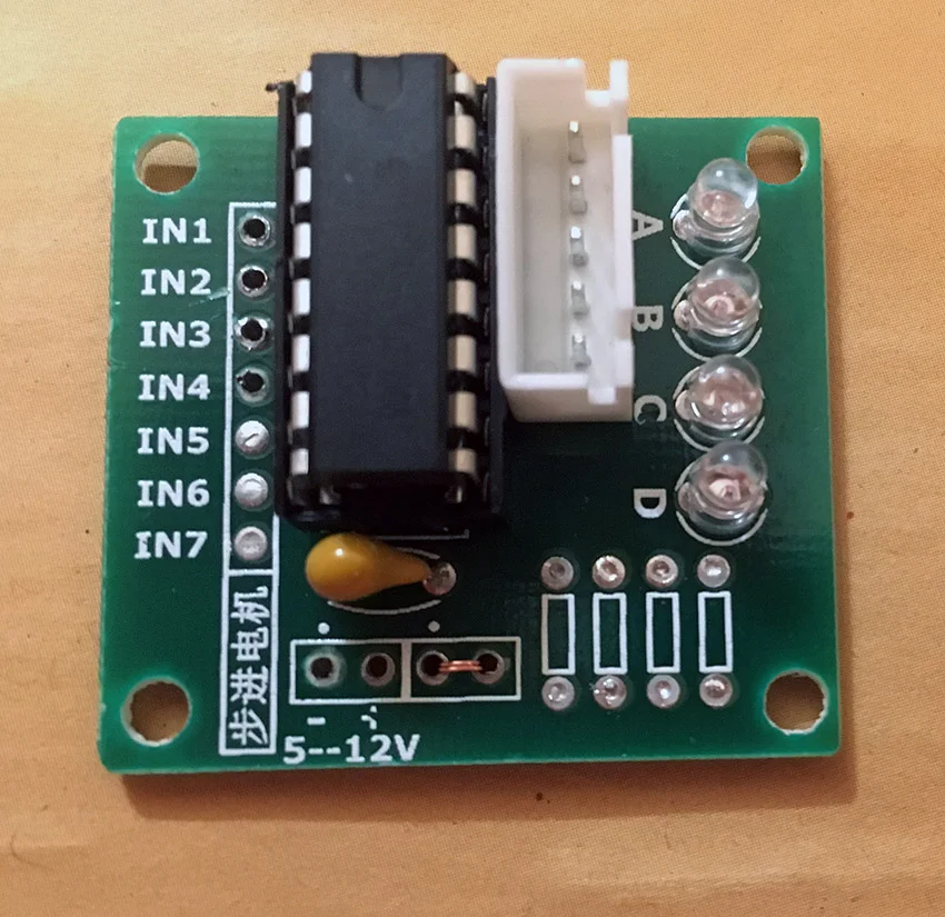
I put everything on a piece of prototype PCB. I desoldered all the pins from motor drivers and soldered leads directly on them. Do not forget to close the jumper pads on the driver.
I also removed all the resistors from driver pcbs - to shut off the LEDs. Could have removed the LEDs but resistors seemed to be easier option.
All pcbs are mounted in the winder with double sided mounting tape. USB connector is glued in with superglue and everything is then covered with midplate. USB PCB needs to be trimmed in order to fit in. I filed it down from both sides carefully. Base is glued together with superglue.
All other mounts are done with M3 screws and M3 square nuts.
Every watch holder can be set to run counter clockwise, clockwise or be off. It runs 10 minutes and then waits 50 minutes.
Setting the winder:
After programming the chip, nothing turns. Press button for more than 0.5 s. Press again with short press. The LED flashes - top left winder is set to run CCW. Press again with short press. The LED flashes twice - top left winder is set to run CW. Press again - no LED. You can scroll the CCW-CW-idle as many times as you want. Then long press sets the desired program for the winder. Another series of short presses scroll the settings for top right winder. Long press to set it. Another series of short presses for bottom left, confirmed with long press and the same for bottom right one. It looks complicated but it is not.
Long - short - short - short ... set with long - short - short .... set with long - short - short .... set with long - short ... set with long. Winder starts moving after the last long press.
It can be set as many times as you want. Settings are stored in EEPROM.
Parts Used:
Motors and drivers: http://s.aliexpress.com/JVjyIzaQ
ATMEGA328P-PU: http://s.aliexpress.com/JrMNBRjM
16mm LED Light Push Button: http://s.aliexpress.com/uMJjymma
Pick the 5V version. Do not forget to buy the socket for pushbutton.
Power adapter with MicroUSB socket: http://s.aliexpress.com/32ueyamm
Double Sided Prototype PCB Breadboard: http://s.aliexpress.com/7nEbeIZv
MICRO USB To DIP Adapter: http://s.aliexpress.com/VFbmaeAv
28 pin IC Socket
10 M polarised capacitor
0.1 M ceramic capacitor
M3x10 screws with half round head 20 pcs
M3x10 countersunk screws 4 pcs
M3 square nut 16 pcs
Bearing 623 inner diameter 3mm, outer diameter 10 mm, width 4 mm 8 pcs
Printer Brand: Prusa
Printer: I3 MK3S
Rafts: No
Supports: No
Resolution: 0.3 mm
Infill: 15%
Holes for mounting the bearings should be tapped with M3 tap.
ByZED4EverLikes313Downloads5.2K

 ByAdam Záhořák ZáhořákLikes39Downloads258

 ByVC_DesignLikes271Downloads753

 Bywibot-3dLikes0Downloads515

 ByMatthew_GhostLikes350Downloads939

 ByfifindrLikes500Downloads4K

 Bymrfixit_324954Likes65Downloads473

 Bylab-96Likes0Downloads104

 ByDan Schwartz SchwartzLikes744Downloads3.4K

 ByBrokentooth_designsLikes83Downloads450

 Byvc-designLikes0Downloads3.2K

 ByUpcrid3D_1585693Likes808Downloads2.1K