



Còi Tàu Hơi Nước Mini
 ByfifindrLikes500Downloads4K
Build another version of this model.
 Đế trượt cải tiến tăng dung sai (Increased Tolerance Base Piece)Byanycreal3d_4001011 · 05/02/2026
 Vise adapter NOW KISS (*^。^*)BySatyr · 04/28/2026
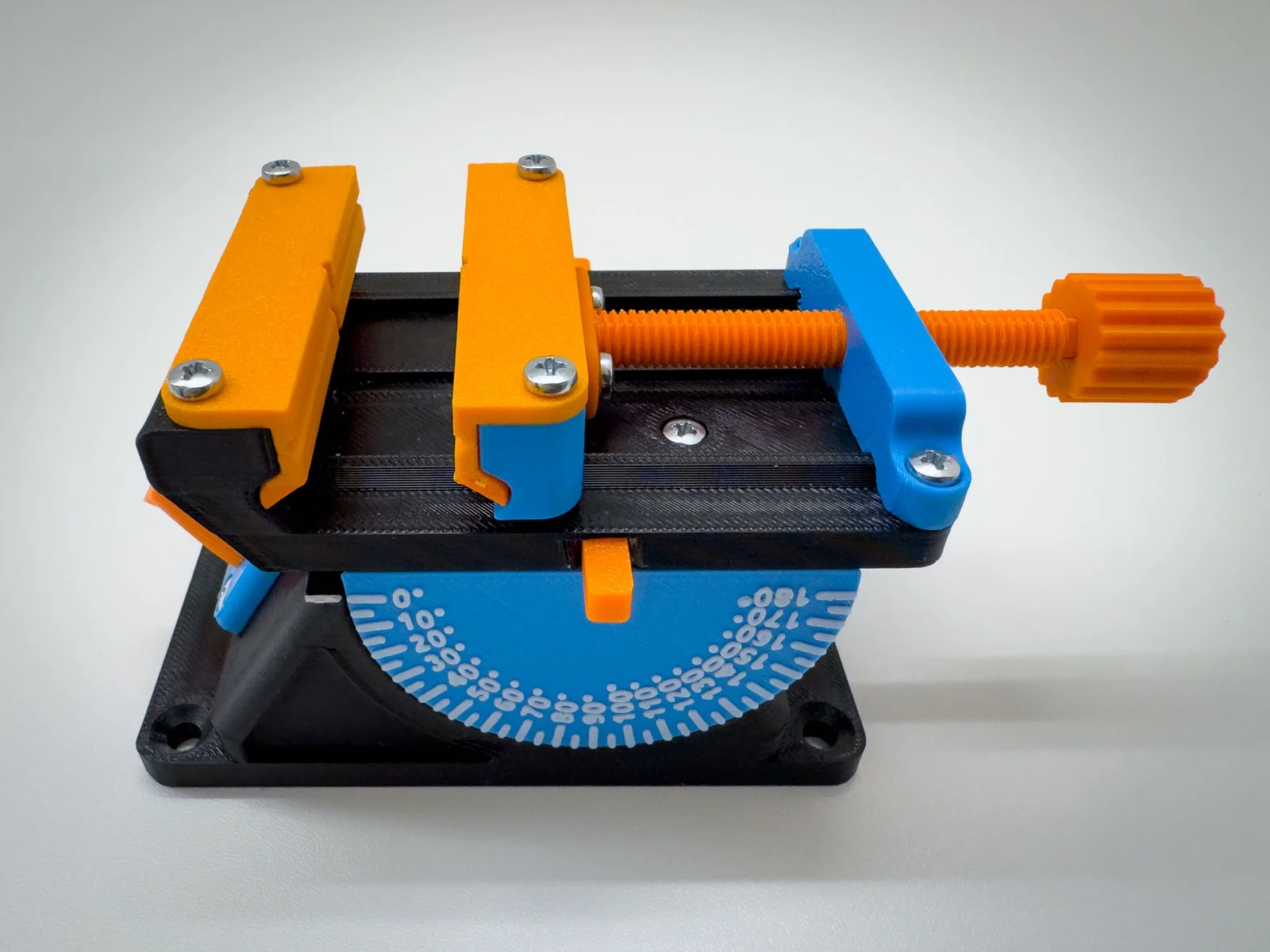
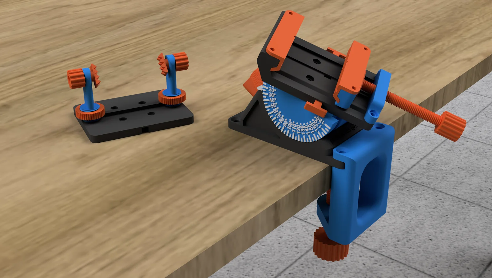
The vice can be adjusted in two different angles and there are several attachments that you can easily change, if you don't like the attachments I have made you can make one yourself, with the drawing with the dimensions as a PDF in the files.
To adjust the angle in height, you just have to turn it, the other angle can be adjusted by pressing the two levers on the sides. When you release them, it locks again. (10° steps)
All together requires about 210g of filament. (Main: 100g, PCB Attachment: 30g, Vise Attachment: 45g, Table holder: 35g)
Print settings:
I have printed everything with 0.2mm layer height. All parts are correctly oriented and the parts that need support are labeled with support. Two small parts require 100% infill, these are also marked. On the Angle Main, you can change the color from the height at which the font changes.
Parts that cannot be printed:
Main: 10 M3x10mm screws, 5x20mm spring.
Table Holder: 2 M4x20mm screw
PCB Attachment: 2 M3x10mm screw
Vice Attachment: 9 M3x10mm screw
Main:
1. first put the gear wheel and the rod into the main part as shown in the picture.
2. then screw on the cover and the turner.
3. Push in the main angle and turn the wheel until it is straight.
4. insert the rotator and the holder and screw on, not too tight, it must hold well but still be movable.
5. finally insert the two clamps and tension a spring between them.
Table holder:
First screw the screw into the part, then screw the clamp onto it and then screw it to the main part with the two M4 screws.
Vice Attachment:
1. put the cover on the screw, then screw it into the part shown in the picture and put the wheel on it.
2. then into the pusher and fasten the cover with two screws.
3. now insert into the plate and screw on the 3 screws shown in the picture.
4. finally screw the two covers onto it
PCB attachment: (design inspired by squinn)
Screw together as shown in the picture (don't forget to screw on the wheel).
Finish:
Screw on the desired attachment with 4 screws.
ByfifindrLikes500Downloads4K

 ByVC_DesignLikes679Downloads3.6K

 ByDan Schwartz SchwartzLikes744Downloads3.4K

 Bychubbs8697_2027893Likes585Downloads1.7K

 Byquibeck_3353173Likes965Downloads1.9K

 ByChris_17729Likes138Downloads307

 ByRungeKuttaLikes229Downloads1.2K

 ByEadubsLikes228Downloads1.3K

 ByWolf_115355Likes513Downloads8.4K

 ByJeremyVillalo_760366Likes68Downloads765

 ByZED4EverLikes313Downloads5.2K

 Bykjus_448782Likes314Downloads673