


Mô hình thành phố Atlantis từ series Stargate Atlantis
 ByMartinLikes2.4KDownloads8.8K
Build another version of this model.
Unimog RC
This is a subset of my new RC truck project that should allow to build a fully functional RC 4-wheel drive truck, based on the UNIMOG 5023 chassis (at 1/10 scale). I'm trying to build the 6 meters version.
I am printing again most of the design because I made a lot of modifications trying to ease mounting and also solve a few design issues. So I'm releasing the gearbox.
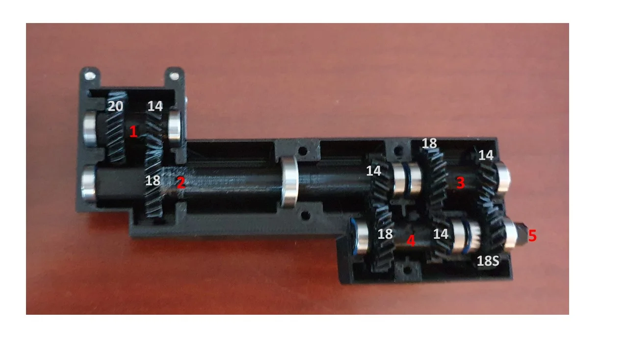
The gearbox uses 6 steps to get 5.47 to 1 reduction.
As in my other RC car designs, I'm using the airplane propeller mode on my 2216 motor with the 2 aluminum parts that are provided with the motor. So, the stator is at the back (and I do not use the motor’s shaft) and the rotor in the front. The motor is mounted onto its support using the cross shaped aluminum part.
The pinion mounts on the 2216 motor using the provided screw mount intended for a propeller that attaches to the rotor’s casing. Once screwed on the propeller mount the pinion does not really need to be secured with a nut. I've preferred to extend the pinion by a sort of shaft that is anchored in a ball bearing inside the gearbox. The idea is to make the assembly less flexible.
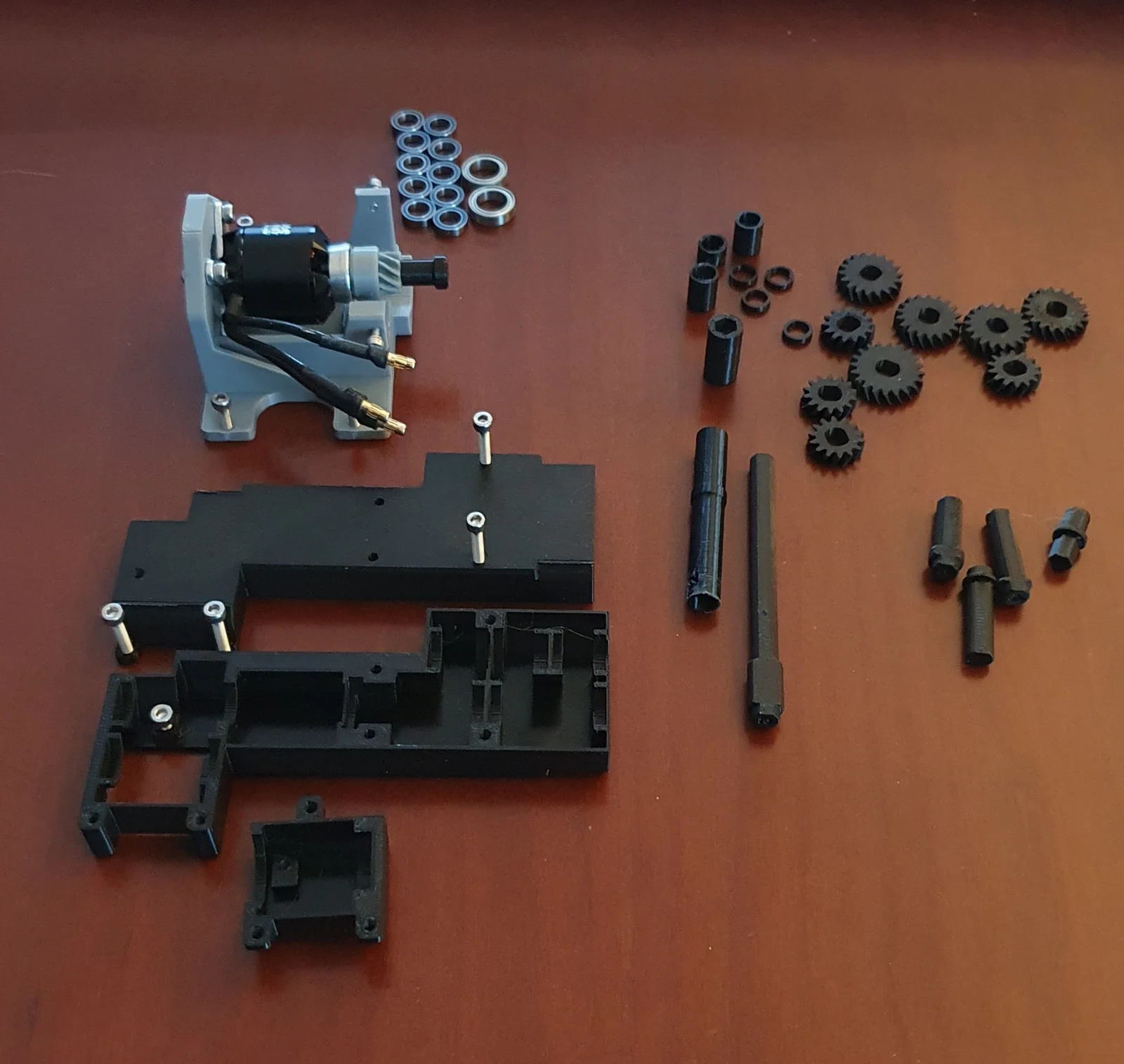
This design uses a set of M3 hex screws of different lengths.
Please try a few lengths and find the most suitable one (not to short but also not to long). I cannot really measure all the screws ;-)
Use the right housing as the base of your mount ; the axles and the spacers have embossed numbers.
All the gears are helical gears.
The pinion has 10 teeth, and each axle assembly features a set of 2 gears, one 20 (axle 1) or 18 teeth (other axles) gear and one 14 teeth gear. Reduction is 0.78 per axle assembly (exception is axle 1 at 0.5). Axle 5 is the output axle, and it carries a hex connector that will link to the 2- speed automatic gearbox (new design to come). All axles use two 11x7x3 ball bearings each. 11 is the external diameter and 7 is the inner diameter while 3 is the BB height (MR117-2RS).
The pinion axle uses one 6700ZZ ball bearing (15x10x4). There is another one in the middle of axle 2. So you need 10 x MR117 and 2 x 6700ZZ.
Gearbox assembly instructions:
Assembly steps for each axle:
Assemble the left and middle housings with one small screw after putting in the 6700ZZ BB .
Complete the assembly with 4 more screws. Do not use the middle screw holes (see pictures); they are intended attach the gearbox to the gearbox bracket ; you can see the full assembly on the chassis in the last picture.
I'm also providing the motor support as it is belongs to this sub-assembly. The gearbox is secured to the motor support with 2 small screws.
Mounting aids: see the pictures
Printing tips:
I retain my naming convention for parts:
XXXnn-kk-name
XXX = sub assembly
nn part number within this assembly
kk number of instances needed in one single instance of the sub assembly
I used PLA for all parts.
ByMartinLikes2.4KDownloads8.8K

 ByMonomoLikes357Downloads3.7K

 BySoarpixLikes739Downloads2.9K

 Byancilod142_2166504Likes320Downloads1.6K

 ByWanderingJui_3925173Likes39Downloads1K

 Byplasmarob_300405Likes252Downloads2.1K

 ByG33kt3chstudioLikes114Downloads393

 ByPariDot_92080Likes71Downloads1.1K

 ByAlMonLikes103Downloads980

 ByGameFan_195116Likes78Downloads332

 Bychrisskinner_491541Likes132Downloads1.4K

 BySoner Güler GülerLikes96Downloads1.2K