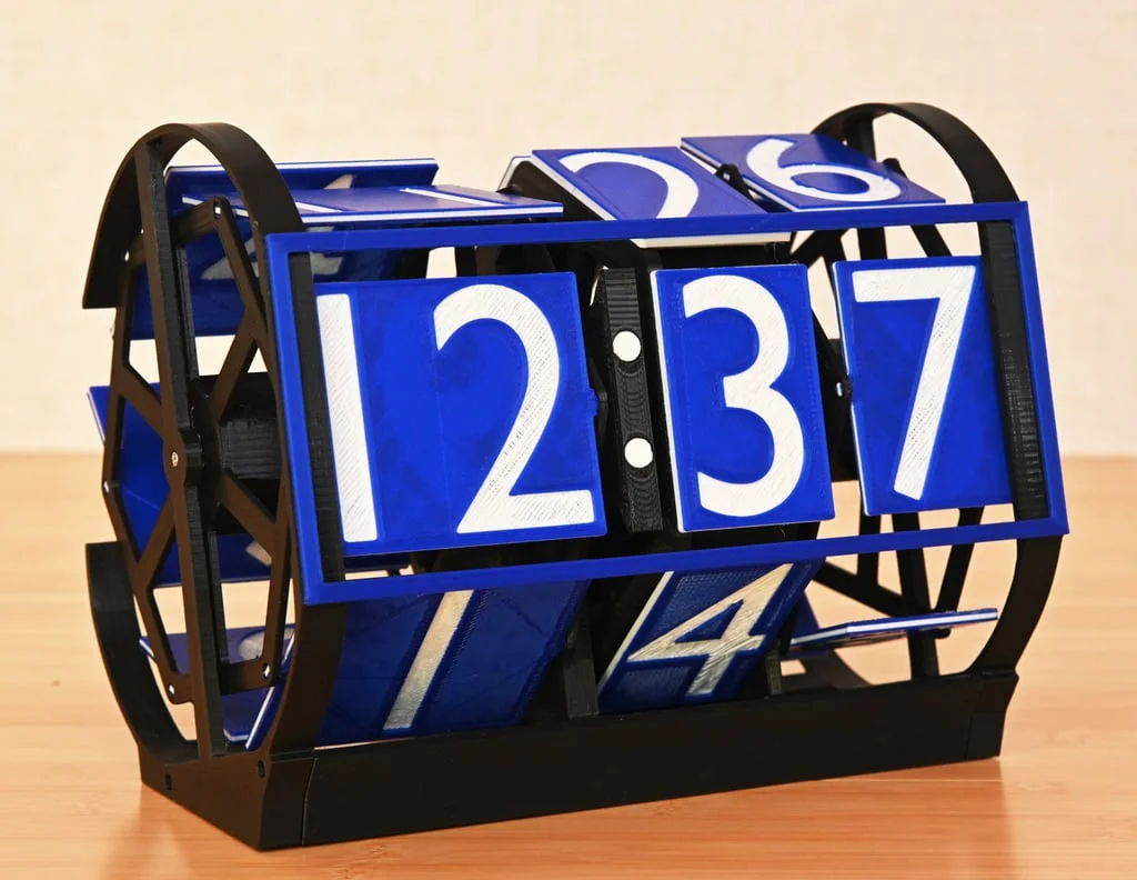
I developed a new clock mechanism to address the issues present in existing mechanical clocks. Famous split-flap displays exhibit undesirable parting lines in the text, and their display surfaces cannot be tilted as they rely on gravity. Numechron-type clocks feature a relatively small display area compared to the body size, necessitated by the large wheel inside. This "Non-Split Flap Digital Clock" offers numerous advantages, which include:
- The flip rotating mechanism reduces the number of flaps, making it possible to decrease the size of the wheel while ensuring the display area is sufficiently large compared to the body size.
- The display surface is tilted at 15 degrees for better visibility.
- The motor is installed inside the wheel of the tens place for minutes, ensuring there are no protruding parts on either side or the back.
- A one-way hook (ratchet) mechanism enables the automatic alignment of the ones place for minutes. This alignment is performed every minute.
- Time adjustment is made easy by manually rotating the wheels. Both the hour and 10-minute wheels can be rotated in both directions.
- All essential parts can be printed out with relatively small 3D printers (180x180mm). It does not need support structure at all. Filament change during print enables to give multiple colors for flap parts.
Mar 17, 2024 : Optional parts for skeleton version are now available. Two skeleton side frames are modified, and the colored front frame is added. Other parts are identical to the cased version.
Video
Supplies
Material
- 28BYJ-48 geared stepper motor and driver board comes with. You can find at Amazon, AliExpress
- Assortment of 2mm tapping screws. You can find at Amazon, AliExpress
- Any microcontroller (Raspberry Pi Pico, Arduino nano, ESP32, etc.) All microcontrollers shown above can be programmed using Arduino IDE, and program is compatible except port connection.
- Lubricant (silicone grease)
Tool
- Screw driver
- Soldering iron (if you use microcontroller without pin headers)
- knife / scraper / file to remove debris / smoothen surfaces / chamfer corners of printed matter
- Drill bit set. I used diameter = 1.5, 2.0 and 3.5mm bits for this project
Print flaps
Change the filament during print to give different color to the numbers.
- The thickness of the flaps is 3mm, and the depth of numbers is 1mm. Therefore, you should change the material before 1mm and after 2mm. I set pause at 0.8mm and 2.2mm from build table.
- If you use Cura Slicer, you should specify the "Pause at height" function in descending order.
- Firstly check if your setting works well for your printer, by using "single-flap-for-test.stl".
- For "10min-flaps.stl", you do not need to change the filament twice because these are single sided.
Finish
- Inspect and clean up the axes of flaps at both side. It is very important to make the flap rotating smoothly.
- Chamfer the top edge of the both side of flaps. This edge touches the guide of the flaps that regulate the pose of flaps (the frames at both side) and makes the rotation of hour and 1min rotors smoothly.
Print and finish essential parts
Print
- Print all parts with supplied posture.
- Support structure is not necessary at all.
- Length of "main-axis.stl" exceeds 180mm (Still within 200mm). Therefore, place it diagonal on the build table when you use a small printer.
Finish
- Remove debris and blobs well, especially around the axes, holes and sliding surfaces.
- Especially, inside surfaces of flap guide rails of "left-frame.stl" and "right-frame.stl" should be very smooth to avoid unintentional stack of the clock.
- Clean holes with drill bits. Use 1.5mm drill bit for the holes engaging the tapping screw. 2.0mm for through holes of screws.
- The holes for the axes of flaps can be cleaned using 3.5mm drill bit. Please be careful not to break the parts.
Subaassembly
Assemble 3 rotors. Each rotor consists of two parts.
- Flaps can be attached after the assembly by the flexibility of rotor frame. Please make sure that flaps rotate very smoothly. See attached video.
- Insert "10min-flaps" (actually these are not flaps) to the "10min-rotor". If flaps slide out, use glue.
Assemble intermediate frames (1 and 2).
- Preassemble the intermediate frames as shown in the pictures above.
- Hide and fix the cable of the motor using “cable-cover.stl”. If the cover is too long, cut it.
- Confirm the smoothness of the all parts.
Put the All Parts Together
See assembly guide video (7min).
- Basically, assemble parts from left (hour) to right (1min).
- The rotating flaps can be attached afterwards owing to the flexibility of the flap holder (rotor).
- Most part is 60degree rotational symmetric and you do not need to care about the position, except 1min rotor because it is pentagonal shape. It has "0" marking at left side.
- Set gears of the carryover mechanism to the status of "just after the carryover". When the gears are at this position, rotors can be assembled that "0" is facing front.
Adjustment
- To adjust the height of digits, tune the angle of the adjusters at the back of the clock. Stronger force moves the digit lower.
Microcontroller
Circuitry
- You can use any microcontroller. I use Arduino nano and Waveshare RP2040-Zero. See connection in the picture above. This circuit is common for most clock projects of mine, such as "Triaxial Numechron Clock" or "Digital Geneva Clock".
- The accuracy of the clock depends on the type of oscillator on the microcontroller. RP2040-Zero is more accurate than Arduino nano because it has crystal oscillator. (Arduino nano has cheaper but inaccurate ceralock oscillator).
- Housing of Arduino nano and driver board can be found at https://www.thingiverse.com/thing:5145523.
- Housing of Waveshare RP2040-Zero and driver board can be found at https://www.thingiverse.com/thing:6619200.
- I made the modified case to attach it to the back of this clock (see Step 6).
Codes
- "stepper-test.ino" drives the motor continuously. Use to confirm that the motor is correctly connected.
- "forward-back.ino" drives the clock rapidly. The motion is almost as same as clock, but it is fast.
- "clock.ino" is the code for actual use.
If the motor rotates to the opposite direction, change the source code, from
int port[4] = {4, 5, 6, 7};
to
int port[4] = {7, 6, 5, 4};
If you use Waveshare RP2040-Zero board connected as shown above, please change the source code to
int port[4] = {5, 4, 3, 2};
Operation
- By pressing reset button, it rotate back to perform alignment. If the 1min rotor is at irregular position, press reset button multiple times.
- After reset, it immediately advances the clock 1 minute. Therefore, reset button can be used to adjust the clock (1min advance).
Optional parts
Cover
- Bottom cover is attached by a screw at center.
- Top cover is just put on the clock. It is convenient for clock adjustment.
- These parts exceeds 180x180mm (Still within 200x200mm).
Skeleton version
- Use two modified side frames, "skeleton-left.frame.stl" and "skeleton-right-frame.stl".
- Print and stick "skeleton-front-frame.stl" using double-sided adhesive tape.
Case to attach the circuitry
Case for the circuitry is supplied. The case is essentially identical to the following, except extension and screw holes to attach to the clock.
Category: Gadgets




 Bytovelaermans_3355197Likes63Downloads422

 ByDerTapirLikes34Downloads167

 ByAustin Wolt WoltLikes162Downloads377

 ByLecso_113752Likes76Downloads329

 ByTomDDLikes89Downloads573

 ByAlexMuLikes41Downloads324

 ByckthLikes148Downloads2.4K

 ByTangoOscarMik_505113Likes31Downloads246

 ByBroBuilds3D_4455044Likes32Downloads451

 ByxsynaticLikes27Downloads209

 BySimin03Likes84Downloads197

 BykyleschiefferLikes35Downloads395