



Kẹp giữ sợi Filament
 Bytinx_1344834Likes1.2KDownloads6K
Remix of MMU2S Buffer (lấy cảm hứng từ RMU Buffer) By Manzn
Build another version of this model.
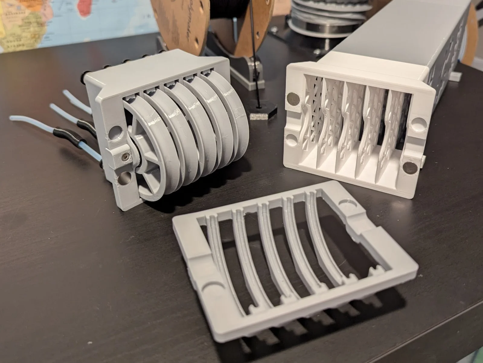
4/27/25 - Added an easy load tray. Insert this in place between the top and bottom and you can then load your filament by pushing into the PTFE tube to reach the MMU without removing the top of the buffer. Once all filament is loaded, remove the insert to print.
8/8/24 - updated magnetic_mmu_buffer_top with proper tapered PC4M10 threads. The item I remixed has incorrect threads for this connector. My thread design can be hand-turned in.
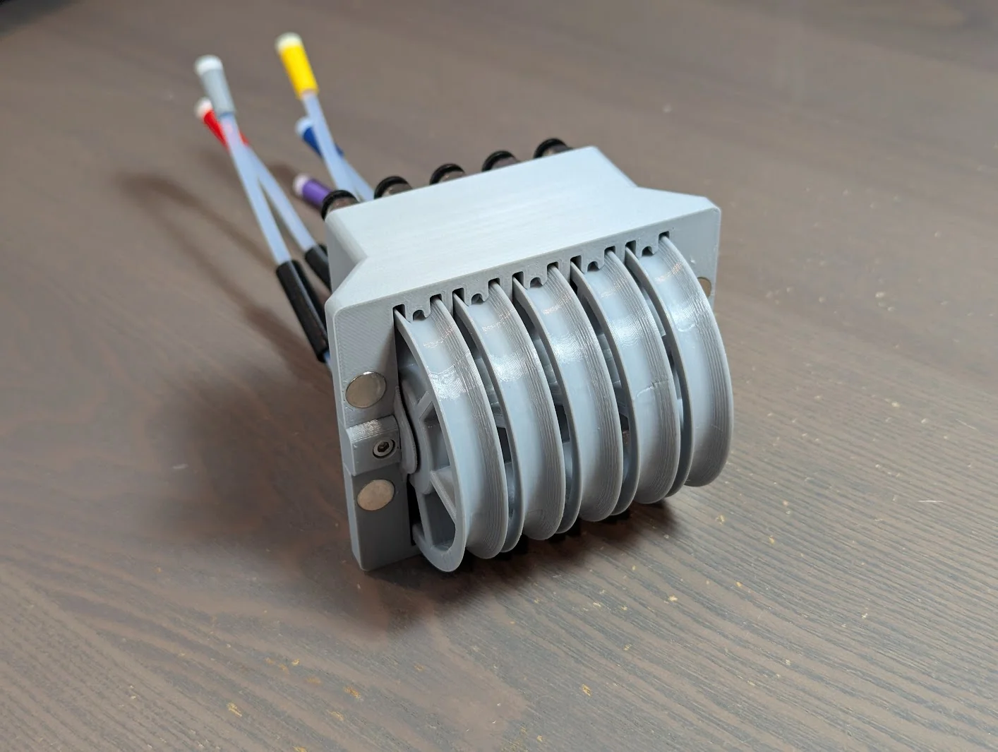
This is a remix of Manzn's MMU2s buffer to have a magnetically mounted top/manifold and no wrap around the wheel for a very low friction path through the buffer. In fact, I found that my filament was preferring to flow out towards the spool vs fill up the buffer so I had to introduce a small bit of friction between the filament spools and the buffer assembly. The amount introduced by this piece is negligible but it stopped the filament from pushing back out towards the spool and now fills up the buffer properly. Usually friction is a problem but not here.
Mounting tabs are generic. If you want to build mounts, the footprint of the mount tab holes are as follows:
4mm holes
250mm high x 85mm wide - center to center measurements
Print all pieces and additionally you need wheels. I used these wheels as they don't have a drastic overhang that may result in rough printed results: https://www.printables.com/model/313118-improved-spool-wheel-print-without-support-for-rmu
All pieces,d minus the loading tray, print without supports as oriented. PCM10 connector holes are designed with sequential bridging and do not require supports.
Files are larger in size as I export these from Fusion360 with the highest resolution possible for the cleanest curves in the print.
This uses the following hardware:
(2) M3x10 socket head screw
(2-8) 10mm x 2.6 rare earth magnets - two sets keep my lid put nicely in the vertical orientation
(5) 608 bearings (skate/rollerblade common bearings - use the cheap ones)
(10) PC4 M10 connectors
Easy printed axle is kept in place by end blocks.
Middle and bottom glue together with CA (superglue).
Magnets glue into place with a drop of CA glue.
Easy loading tray prints as oriented with supports. As this is not load bearing, print in PLA for cleaner overhangs. Try without the magnets in this piece as I found I didn't need them.
I removed the grease from the bearings so they turn easier and left the covers off.
Lid also uses PTFE inserts to help keep the path aligned and to minimize friction. There is a tube cutting jig(see pics). May need to use needle nose pliers to push these in to place.
I use these spool rollers and this shelf rack design for my filament.
Also use this flared end for PTFE tube loading.
Bytinx_1344834Likes1.2KDownloads6K

 ByltloweLikes26Downloads124

 Byarhi_585078Likes64Downloads545

 ByfilamentalistLikes71Downloads111

 By3DSourcererLikes48Downloads380

 Byprusa-researchLikes0Downloads2.7K

 ByEllieColvig_3665985Likes25Downloads190

 ByLeifLumbyHenriksenLikes3Downloads10

 Bydet-manLikes0Downloads175

 Bygummiegecko8477Likes0Downloads167

 ByteteomatLikes0Downloads138

 BydalleLikes0Downloads149