



Kẹp giữ sợi Filament
 Bytinx_1344834Likes1.2KDownloads6K
Build another version of this model.
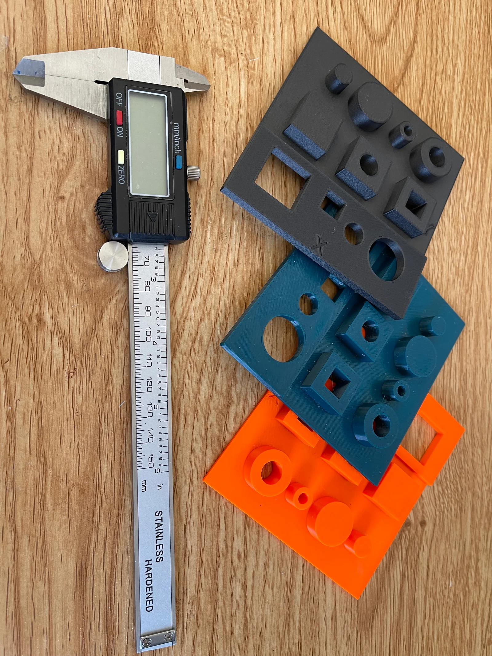
I experienced frustration when trying to accurately redimension a model to take shrinkage/expansion into account, the regular XYZ test model dimensional error did not match the error seen on the real (non-test) model, so I had to do it over again using the model itself. Furthermore, I found that the error on hole diameters and shafts was not the same as seen on exterior dimensions.
The goal of this model is to try to develop a model in which the adjustment parameters derived from a test model can be applied to the real world models. This is to save on time and materials. Furthermore to develop parameters that can be applied to the filament profile, applied to all models printed with the same material.
Prusa Slicer contains no fewer than 3 places where dimensions can be adjusted, adding to confusion. They do not all work the same.
At this moment I am focussing on the “shrinkage compensation” of XY and Z found on the filament profile > advanced page of Prusa Slicer. It's clear that there is an assumption by the developers that X and Y shrinkage will be the same, distinguished from Z.
I took the view that my difficulty might be because the XYZ Cube test model was too small, and certainly did not include any holes. This model is 100 mm in overall size, and maybe it will be more applicable to the real world.
This model is an attempt to overcome the observed shortcomings.
The exterior dimensions of the model are 100 mm x 100 mm x 2mm and 5 mm Z height.
In 3 rows back to front.
A) Rear Row: 2mm base.
a) circular shaft objects of 10 mm and 20 mm diameter, and 10 mm in height.
b) circular shaft objects of 10 mm and 20 mm diameter, with interior holes 5 mm and 10 mm diameter.
c) Rectangular column objects 5mm thickness x 100m height, each with 5mm centrally located holes with axis horizontal w.r.t. the bed. One of them is oriented so the hole runs in X direction, the other object in Y direction.
B) Middle Row: 2mm base
3 x square objects of Z height 10 mm from the bed.
a) (left) square peg 20 mm square
b) (middle) square peg 20 mm with circular hole 10 mm diameter
c) (right) square peg 20 mm with square hole 10 mm on each side
C) Front Row with Base 5 mm high
a) Square hole 20 mm
b) square hole 10 mm
c) circular hole 10 mm diameter
d) circular hole 20 mm diameter
Usage:
(Print directions).
1. Material: Your test material, using its standard filemanent profile, which should be calibrated for extrusion multiplier. I started with PETG, but the whole point is to try this with various materials. Please ensure that your filament is dry before starting, as dampness could confound your results altering the expansion and contraction of the material itself.
2. Print Profile: 0.20 mm structural (medium speed), 15% grid infill, No supports, otherwise all defaults. But feel free to adjust settings to those used by your real world model. The number of perimeters and the amount of infill will surely affect the amount of shrinkage/expansion in some degree. You can try “External Perimeters First” setting, as this is said to improve accuracy. The whole point is to discover what settings you can use to attain better dimensional accuracy
4. Printer Profile: Your printer standard profile.
5. Physical printer setup/calibrations.
====
Assessing the results:
Measure every dimension on the finished print using Calipers with 4 digits on the display, and record the measurements in a spreadsheet. This will make it easier to calculate the percentage errors and correction values with fewer typographical errors. You could cut and paste the following table into your spreadsheet to save a little time.
Row
Dimension Object
A: mm
Model
B: mm
as Printed
error
A-B
(mm)
(A-B)/A
Unitless
100*((A-B)/A)
Percentage
1 Rear
Plate height
2
ie 2.890
1
Circ Shaft 1 diameter
10
1
Circ Shaft 1 height
10
1
Circ Shaft 2 diameter
20
1
Circ Shaft 2 height
10
1
Circ Shaft 3 OD
10
1
Circ Shaft 3 ID
5
1
Circ Shaft 3 height
10
1
Circ Shaft 4 OD
20
1
Circ Shaft 4 ID
10
1
Circ Shaft 4 Height
10
1
Rect Shaft (1) X
10
1
Rect Shaft Y
5
1
Rect Shaft X
10
1
Rect Shaft Hole Diameter
10
1
Rect Shaft (2) X
5
1
Rect Shaft Y
10
1
Rect Shaft X
10
1
Rect Shaft Hole Diameter
5
2 Middle
Squ Shaft 1 X
20
2
Squ Shaft 1 Y
20
2
Squ Shaft 1 Hole Dia.
10
2
Squ Shaft 2 X
20
2
Squ Shaft 2 Y
20
2
Shu Shaft 2 Squ Hole X
10
2
Squ Shaft 2 Squ Hole Y
10
3 Front
Squ Hole 1 X
20
3
Squ Hole 1 Y
20
3
Squ Hole 2 X
10
3
Squ Hole 2 Y
10
3
Circ Hole 1 Dia.
10
3
Circ Hole 2 Dia
20
3
Plate Height
5
From this You can calculate the error in dimensional reproduction, and the correction factor to be plugged into filament profile> advanced > Shrinkage compensation. It's simply the negative of the error (percentage).
You can also try the effects of altering the number of perimeters (vertical shells) and the amount of infill and “External Perimeters First”.
Then reprint the test model.
Hole diameters will need to be assessed, and if beyond tolerance they will need to be adjusted in the Modeller (such as Fusion 360), as Prusa Slicer has no tool to do this.
Shaft diameters and holes will be affected by
Bytinx_1344834Likes1.2KDownloads6K

 ByGeek5DLikes147Downloads482

 ByreddLikes216Downloads2.2K

 ByJasonOlliff_519145Likes241Downloads2K

 ByKRYS_3DLikes8Downloads43

 Bygafyx3dLikes0Downloads116

 ByswimLikes0Downloads104

 Byarhi_585078Likes64Downloads538

 ByFonnPrintsLikes4Downloads17

 ByltloweLikes26Downloads119

 ByHanzo3dLikes155Downloads412

 ByPengLordLikes32Downloads109