




Hộp Trượt Tham Số Tùy Chỉnh – Giải Pháp Lưu Trữ Thông Minh
 ByRobertoGalloc_356815Likes549Downloads1.8K
Remix of Tệp mô hình Multiconnect cho Multiboard By DavidD
Build another version of this model.
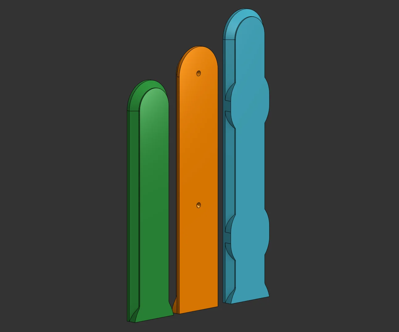
This is a parametric implementation of the multiconnect “connector back” negative, i.e. it's a customizable model of the female channel on the back of multiconnect-mounted designs. The negative is used by boolean subtracting it from the back of your own parts, “cutting” the necessary channel.
A number of sample negatives are provided, but most likely you want to customize your own with the instructions below.
Height: The height of the negative, top to bottom.
Repeat Indent: Repeats the inner indent down the part. This indent (which is a bump once the negative is applied) “locks” a connector in place, so this option is used for parts mounted with more than one connector.
Indent Spacing: The spacing between the repeated indents, in 25mm units.
Quick Change Cutouts: Enables cutouts in the channel to slot in a connector in mid-way, rather than sliding it entirely from top to bottom. To be used by parts mounted with more than one connector, follows the indent spacing option.
Quick Change Offset: The offset of the quick change cutouts relative to the indents.
The design and option limits are generally in-place to prevent non-functional parts, though the document can always be copied and modified if you find them too restrictive.
ByRobertoGalloc_356815Likes549Downloads1.8K

 BymindthelightLikes251Downloads388

 ByVC_DesignLikes721Downloads2.9K

 ByUpcrid3D_1585693Likes808Downloads2.1K

 ByWilko_SLOLikes935Downloads2K

 ByTater_364200Likes486Downloads1.6K

 ByfifindrLikes709Downloads1.7K

 Bywhilex_1739192Likes644Downloads1.1K

 ByGi_TLikes801Downloads1.3K

 ByzeroflowLikes186Downloads1.2K

 ByMatthew_GhostLikes350Downloads938

 ByWolf_115355Likes513Downloads8.4K