



Grippy Broom Holder
 Byvc-designLikes0Downloads3.2K
Build another version of this model.
This is a fast printing 608 bearing which has less play than print-in-place options. For print settings, you can probably just use your slicer's default 0.20 mm layer height setting, with two wall loops and rectilinear bottom infill. Sparse infill is irrelevant; there are no spaces to fill.
The advantage of these over print-in-place options are:
The disadvantage is that it's a bit more of a fuss, and they take a little longer to print than, for example, my three part fast 608 bearing.
There are a few reasons that I chose a single roller for this design, rather than trying to emulate a traditional ball bearing with multiple rolling elements. The first is that while those multi-roller designs are really cool, I find that the rollers don't actually behave as intended when printed on FDM printers. They mostly tilt around and jam, so that all of the rollers act as a single element anyway. On the other hand, they're slow and somewhat difficult to print, and they would make assembly an enormous pain in this design.
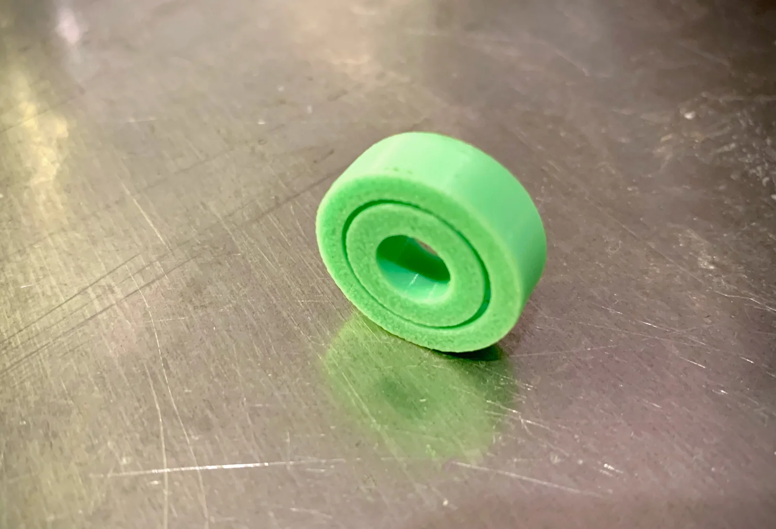
Note the pieces called “bore hollow” and “outer hollow” in the 3mf. These are the larger and smaller pieces which each have two walls with a gap between them. Place these on a work surface so that the openings between the walls face up, like this:
Now take the “roller” (the ripply ring) and coat it liberally with the grease of your choosing. Insert it between the other two pieces, like this:
Now take the “outer solid” piece and press it into the “outer hollow” part. Do the same with the “bore solid” piece, pressing it into the “bore hollow” part.
Turn the bearing back and forth to make sure to spread the lubricant around.
The solid pieces should press tightly into the hollow parts. You should need to really lean into it or use a vice to press them together. If they slide in too easily, try adding a very small amount of positive XY compensation to thicken everything up. If they're loose, they may come apart under load.
Conversely, the roller should not fit tightly, but shouldn't have much play either. It should slide in with very little force, barely grazing the walls. If it fits tightly, reprint it with a small amount of negative XY compensation.
Byvc-designLikes0Downloads3.2K

 BySeppoTakaloLikes960Downloads1.9K

 Byrb_200934Likes48Downloads1.1K

 ByZED4EverLikes313Downloads5.2K

 ByfifindrLikes500Downloads4K

 ByVC_DesignLikes679Downloads3.6K

 ByKNIN_CustomLikes112Downloads437

 ByDan Schwartz SchwartzLikes744Downloads3.4K

 ByUpcrid3D_1585693Likes808Downloads2.1K

 ByWilko_SLOLikes935Downloads2K

 Bychubbs8697_2027893Likes585Downloads1.7K

 Byquibeck_3353173Likes965Downloads1.9K