


Adapter ống PTFE cho MK4 Nextruder PC4-M5 có thân dài - kiểu Collet
 ByltloweLikes26Downloads123
Build another version of this model.
Update Feb 14, 2026 - See my alternate space saving design of the MCS 2 here. I like the original one (the MCS here) and I think the original looks better, especially with the Slot buffer, but the new one saves a ton of table space, and sits to the right of a front facing printer. The MCS2 does require the R4 Prusa Buffer though.
Revisions:
Updated Main Parts - Oct 5, 2023
Documentation Updated Here and Online Video: April 2024 - now tested with new MMU3 and MK4.
This is a long youtube video on the MMU3 assembly, but you can see the MCS in action here with the MK4 in several places below in the video:
Custom Multicolor System Intro: (1:10:36)
Custom Multicolor System Benefits: (1:11:25)
Preloading Filament Again: (1:14:05)
MMU3 New Buffer: (1:06:00)
Printing Five Color Test Print: (1:14:43)
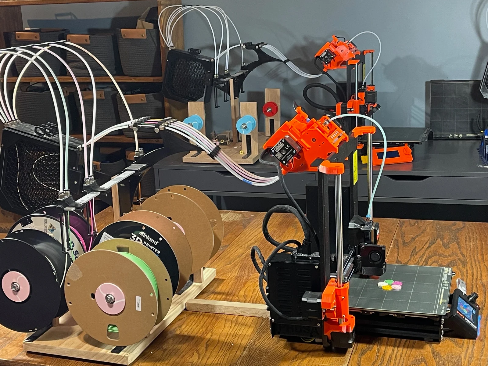
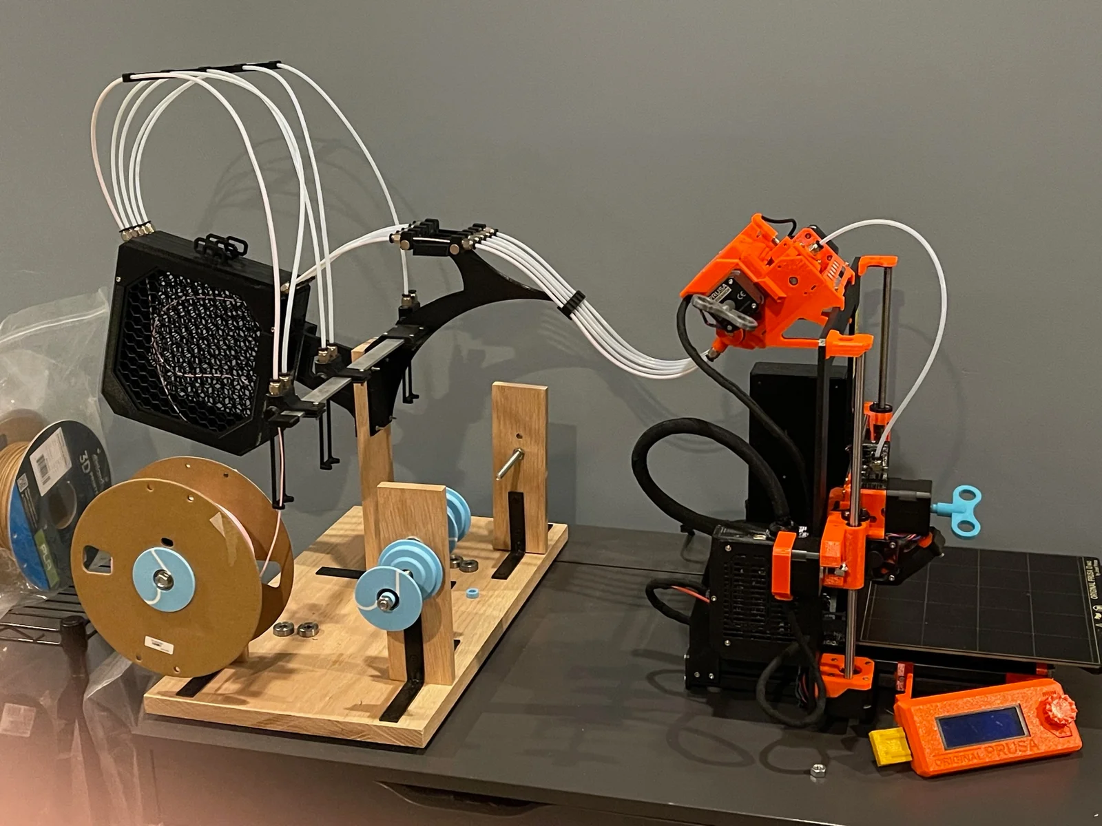
This has gone through several iterations and is a solution to fully control the filament path behind the MMU and has been now tested with the MMU3 with the MK3S+ and now the MK4 and works fine unchanged for both. This page describes how to set up my MCS for managing the filament path behind the MMU. Follow the detailed instructions I made with many screen shots. The setup here is the roughly the same for the MMU3 or MMU2S as everything happens behind the unit.
Low Friction PTFE Tube Path Design
3mm tubing everywhere with no sharp turns
3mm tubing short tube inside the MMU too
No retraction slippage
‘S’ shaped curve locks filament against walls after a retraction
Filament path is fully locked in place and controlled
No loose tubing and all tubes have an exact prescribed tube length
Open manual adjustment loading slot
Frictionless center bearing spools
Great for cardboard spools
Custom exact fit hubs fit all spool sizes perfectly with no added friction
Ability to add extra friction to enforce buffer loops
PC4M10 connectors everywhere possible
Buffer box PC4M10
Rear MMU connectors PC4M10
Spool termination PC4M10
Easy Spool Access - 4 Spools are at waist level in a group together at the edge of the table with center rods and bearings, with a fifth in the back
Fifth spool is rarely used and is still accessible
Spools 1-4 are right in front of user at waist level
Room for a 6th spare spool
Buffer choice - Prusa MMU3 new buffer or Martin Slot buffer
Either can be used interchangeably
Custom brackets included for each
Portable and compact as possible
Can pick up the entire setup and move as one unit, spools and all
Solid wood base, with overengineered brackets and metal rods
Designed to sit behind printer in a straight line with printer facing to the right
This design uses parts at any hardware store and parts easily orderable off Amazon. They consist of plastic, wood, and metal parts depending on function. I believe I chose the best material for the function. Metal brackets and wood supports make for a much stronger spool holder for instance. I did not try to 3d print everything in plastic if metal or wood made more sense and was faster/stronger/easier and not cost prohibitive. 3D Printing is mostly used for the connections and exact positioning of tubing.
Everything here is my own design except the buffer. You need either the Prusa official MMU3 buffer box or Martin's Slot Buffer box, which is linked. Both are used unmodified so if you have them already you can use them. I also am using some other optional parts which I recommend and link. Please let me know if anything needs to be improved or if you have suggestions. Feel free to add a remix to this. No commercial use however.
The materials for one of these cost me exactly $79 plus PETG filament. Assembly is straightforward and requires a good drill, saw, PTFE cutter, good measuring skills, and about 4 hours. Many items are left over so you have extra materials to make more of these or use elsewhere, so the true cost for one of these is higher if you don't plan to use the extra materials, such as leftover glue, magnets, and screws. The print time is about 15 hours, assuming you already have a buffer box in hand.
I have settled on the use of these Ikea ALEX desk 23 inches deep and 52 inches wide which can be found off Facebook marketplace used for about $90-100. The printer sits in the middle facing to the right with some work area to the right end of the desk. I use an LCD side mounted bracket with it. The spools and buffer setup outlined here sit on the left side of the desk, behind the printer also facing to the right. (You can also have it all face to the left instead.)
There is a 9 inch gap between the printer's back frame and the base board of this setup. Everything here sits on this base board. The base board then extends 11 inches further left to the edge of the desk. The buffer unit then extends a few more inches out to the left, off the desk. The filament cables arch up as high as two feet above the desk. The depth is no more than 20 inches towards the back.
The base board part that touches the table is 11 inches wide, starting 9 inches behind the printer back frame edge, and 20 deep, (although if needed you can use a 10x18.5 inch board).
I am trying not to list parts in two places so revised this listing on 10/5/2023 to only include the three core parts below that really can only be used with the MCS. Just below see the other parts that you will need to grab from other listings.
1x Central Arch (includes four subparts) - This large part connects everything together to the main vertical wooden support. It holds the aluminum bar, supports the open adjustment couplers, and positions the filament path into a rollercoaster shaped S curve behind the MMU3.
3x Hanging Endpoints (and bar end caps) - These attach to the aluminum bar above the spools. They terminate the filament next to the spool with a PC4m10 jack, adds a needed filament guide hole to prevent the filament from going over the spool edge, and optionally allows you to adjust the needed friction against the filament to enforce a buffer loop in the slot buffer if needed. Optionally attach the bar end caps over the ends of the metal bar to prevent the sharp ends from scratching you.
5x Open Adjustment Couplers (use the remix with improved magnets)
An assortment of 5 Spool Centers and spacers of your choice depending on your spool sizes:
5x Spool Centers 50-60mm various generic sizes, and/or
5x Polymaker Spool Centers (54.3mm sized and improved design, fits most spools)
10x Spool Rod spacers (or use ones with polymaker spools for those)
1x short PTFE spacer (included here, but suggest to use the remix that allows magnetic detachment)
One of these Buffer Brackets:
1x MMU3 Vertical Buffer Bracket (for Prusa Buffer Bracket only), or
1x Slot Buffer Angled Bracket (for Martin's Slot Buffer only)
1x PC4m10 rear connector for the MMU3. (For the MMU2S there is a similar part.)
See the collection Used on MMU3 as well for other parts to consider -
https://www.printables.com/@CherryHillTech/collections/502811
You need to provide/print a buffer box. This design supports Martin's Slot Buffer or the new Prusa MMU3 buffer.
The advantage to the Prusa Buffer is that you might already have it, and it takes up less space. The Prusa buffer uses a mechanical wheel to ensure a loop is formed and this is a foolproof way to enforce a loop. I feel this must come at an added cost because the filament is forced to bend tightly to go around the wheel, and this adds friction as well.
The advantage to Martin's excellent slot buffer is that you can print it yourself, it is entirely non-mechanical, lets you see the filament loop inside, and introduces less friction to the path. The loops form naturally on retraction, and when being pulled through it the filament goes in a wide arc with very low friction. I prefer this buffer but I understand it is asking a lot of folks who already have the Prusa buffer printed. In that case I would stick with the Prusa buffer.
I have a solution to add friction in the rare cases on the slot buffer where loops get pushed back to the spool, so that is not a problem with this design. The hanging endpoints in my setup allows you to introduce friction to force a buffer loop if needed with the slot buffer. If using the Prusa buffer I presume you would not need to add any friction as there already is alot and the severe angles going in force a loop. But even with the slot buffer I would add that I rarely need to use the Knobs on the Hanging Endpoints to add friction, and I know which filaments they are - really smooth, slippery, glossy ones. Thus, choosing the Prusa buffer for the extra friction element would be hitting a small problem with a big hammer, and introducing friction in most cases where it would be detrimental.
Both use a single bracket, a slightly different custom bracket I designed for each, to attach to the central vertical wood post. The slot buffer sticks out higher in midair about 7-8 inches further back, while the Prusa buffer sits on the base and sticks out 4-5 inches further off the base. So the Prusa buffer does save 3-4 inches of space if a wall is in the way.
Both have a similar print time of about 25 hours. Both need similar lengths of PTFE tubing but they do vary slightly within a few inches.
In terms of appearance the slot buffer just looks much cooler. You could really customize the appearance of the slot buffer by making the see through interior panels different colors! I would recommend the slot buffer since it looks nicer overall and has no moving parts and introduces less friction, and you can make it now and not wait for your MMU3 kit to arrive.
So in summary if you have Prusa buffer then just use that. If you do not have it yet or have time or interest to print a Slot buffer print the Slot Buffer, but only if you can afford to allow the extra 3 inches of space needed for the Slot buffer.
If you want to use Martins Slot buffer here is a link to get that below. Also get the remix for the inserts.
1x Martin's MMU Slot Buffer (SB)
5x SB PC4m10 inserts (a remix of the inserts to the SB buffer)
See the collection Used on MMU3 for a summary of all parts to consider -
https://www.printables.com/@CherryHillTech/collections/502811
MK3S+ only - Highly Recommended - Improved chimney by Peter Larson with PC4m10, extended PTFE path 1 cm below the chimney into the adapter printer block, and a much sturdier adjustment system. I used this on the MMU2S and never had any problems with the IR sensor. I found the new sensor to have a window of sensitivity that was harder to adjust, so I am using these again on the MMU3 and prefer them over the new MMU3 stock chimney. I think it works so well because the screws on the right prevent the chimney from tilting to the left when the back center attachment screw is tightened. This uses a PC4m10 adapter too.
https://www.printables.com/model/7789-mmu2s-easy-ir-sensor-calibration
MK3S+ only - Highly Recommended - 1-2 cm longer 3mm ID tubing between the selector and extruder
MK3S+ and MK4 - Highly Recommended - 3mm ID tubing inside the MMU with the very short tube there, no camfer is needed either
1x MK3S+ LCD side mount - optional - but suggested (I might also still make one for the MK4 but it is not needed)
MK3S+ and MK4 - optional - Pc4m10 front plate with PC4m10 adapter for the selector. https://www.printables.com/model/77175-mmu2-selector-front-plate-with-direct-pc4m10
Especially if you are using the chimney above, but even if you are not, I also recommend a 1-2 cm Longer tube between the selector and the extruder. Part of the length is because the part above allows you to extend the PTFE into the adapter printer cube, and also because the new firmware doesn't ram and so you can have a more natural curve to the tube that is a bit longer. I also use one with a 3mm inner diameter as opposed to the 2.5 stock one.
Parts from Prusa MMU2S/MMU3 Kit (you should already have these but can more too)
25 feet of 4 outer/3 inner mm diameter PTFE tubing (you will have 46 inches left over) I used this - $12/15
15 PC4m10 adapters - this (you will have 5 left over) $10/14 (this doesn't include the 10 more used in the slot buffer you already have), and get 2 more for use on the selector and extruder if you use those optional mods too
20x 1x10 rare earth magnets - link (you will have 80 left over) $2/9
Superglue (loctite superglue Ultragel control in blue bottle) - link (you will have 1 bottle left over and lots extra in the first) -$1/8
(and PTFE cutter tool you already have)
4x 30mm m3 hex bolts
4x 14mm (ideal) or 16mm m3 hex bolts
2x 20mm (ideal) or 18mm or 25mm m3 hex bolts
10x m3 hex nuts
link (tons of these left over) $22
6x Four inch long metal 5/16 bolts - $6
6x 5/16 washers $1
12x 5/6 nuts (normal not lock nuts) $1
1x 16 inch long .75 inch wide flat aluminum bar mm thick $7
8x 3 inch metal flat brackets with .5 inch wood screws included $12
4x adhesive .75 inch square rubber or felt nubs/feet/pads $3
(and drill and saw, sandpaper/files you already have)
1x three foot long hardwood oak board 2.5 inches wide and .5 inch thick (you will cut this into four pieces)
1x board .75 inch oak board. You will need enough to cut it into a 11 by 20 inches long rectangle. (Scroll below for alternate minimum measurements)
1x dowel or any thin piece of wood nine inches long, or 8.5 depending on length of PTFE tubes
All the wood should be solid oak. Do not use pine or cheap plywood as the wood screws will come out. After drilling the holes you might consider painting it before attaching the hardware!
There are four parts:
Large Arch which attaches the the central wood vertical beam and connects everything
Bar holder top cover to clamp the bar down
PTFE short bracket
Top Bracket to holder the five couplers
The bar holder screws into the arch and the other two are glued on.
The arch part just barely fits on the print bed and stretches into the lower left corner, the top, and the right side of the bed. Warping is an issue with this size. Try to print in warm room if possible or enclosure. I did neither and did have about a 2mm warping on the lower left corner on all but the part was still fine as it didn't impact the screw hole locations. Dont worry if it warps as all of mine did. Print with no priming loops so it fits, and no supports. It just barely fits onto the bed if rotated to the right slightly. Use PETG with 20 infill and 3 perimeters.
Print the bar holder part with snug supports. Print it face up so the top prints nicely. The embedded screw head holes are on the top side of it.
For the main arch part:
.4 or .6 nozzle
up to .35 layer height
PETG (required for strength and flex)
20% infill
3 perimeters
For the rod clamp, and ptfe holder and coupler attachment
up to .3 layer height
PETG (preferred) or PLA
20% infill
2 perimeters
up to .3 layer height
supports snug .35 detach distance painted on only for the underside of the rod clamp (see it in the 3mf)
Printing of Hanging Endpoint Parts and Bar End Caps
You need to print three of these. Each one comes with two plastic bolts. You also need to screw in 2 PC4m10 adapters. These need to be printed in very good quality as there are four screw threads in each. Print with:
.4 nozzle
PETG (required as these flex under use)
20% infill
.2 layer height
.3 detach distance snug supports painted on.
2 perimeters
Use the 3mf which works well. Also print two of the optional endcaps in PETG as well.
Printing of Buffer Bracket Clamp
Slot Buffer version
This prints with no supports, uses two hex nuts and two 20mm m3 hex bolts to secure the sides. The sides are different.
.4 or .6 nozzle
PETG (for strength)
20% infill
3 perimeters
up to.35 layer height
no supports
Prusa Buffer version
This prints with snug supports to support the peg on the end:
.4 or .6 nozzle
PETG (preferred) or PLA
20% infill
3 perimeters
up to.35 layer height
snug supports
ByltloweLikes26Downloads123

 Bytinx_1344834Likes1.2KDownloads6K

 ByPengLordLikes32Downloads114

 BynozeLikes0Downloads135

 Byprusa-researchLikes0Downloads783

 ByLeifLumbyHenriksenLikes3Downloads10

 BywendigoLikes0Downloads123

 Byarhi_585078Likes64Downloads545

 ByfilamentalistLikes71Downloads111

 BytimLikes0Downloads528

 ByGeek5DLikes147Downloads490

 ByanatoliikLikes0Downloads122