


Khuôn Vẽ Sơ Đồ Mạch Điện Tử (Kích Thước Thẻ ATM)
 ByBoonby_1059917Likes659Downloads1.2K
Build another version of this model.
Summary
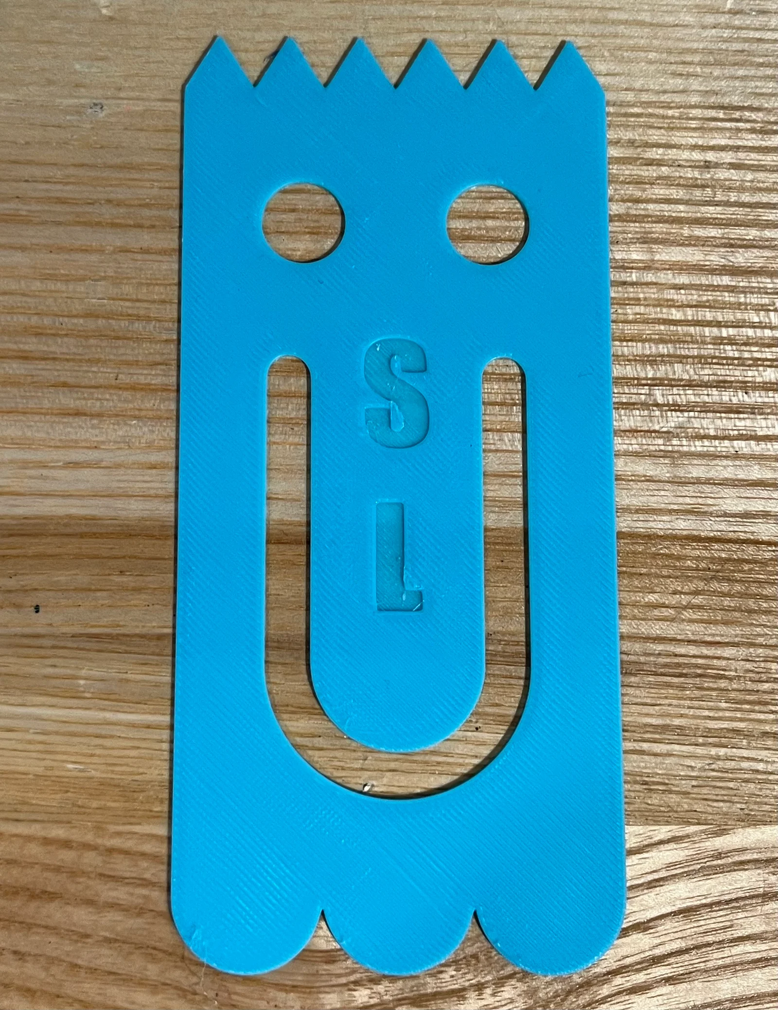
This 129.37x59.74x1mm ghost clip is great as a decorative paperclip, or as a bookmark! Customize it by adding your own initials, and printing it in any color you want! Useful for reading, school, and work, this clip will make your life significantly easier while making your work space much more exciting! I worked with Jusenly Lorthe on this project (@jusenly_4595410).
Objective
Work with a partner to create two identical, exact replicas of the ghost clip on Solidworks, efficiently using the Mirror and Offset Entities tools at least once each. The two projects must be identical, created in the same way click for click. The sketch must be fully defined with zero error messages and have detailed but efficient dimensions as well as relations that decrease the number of necessary dimensions.
Assembly/Construction Instructions
Constraint Box
Using the center rectangle tool marked for construction, create a constraint box centered on the origin with construction lines set to midpoints of sides. Use Smart Dimensions to make the box 129.37mm tall and 59.74mm wide.
Bottom Arcs
Using the three-point arc tool, create three connected arcs along the bottom edge within the constraint box. The left endpoint of the left arc and the right endpoint of the right arc should be coincident with the left and right sides of the constraint box. Using manual relations, apply the tangent relation between the bottom of each arc and the bottom edge of the constraint box. Select the center of the middle arc and the center vertical construction line and apply the coincident relation.
Hold down the Control key and select the centers of each arc. Apply the horizontal relation to all of them. Separately, apply the horizontal relation to all of the endpoints of the arcs.
Use the line tool marked for construction to draw the radius of each arc. Apply the parallel and equal relations to all three radii after selecting them while holding down the Control key. Use Smart Dimensions to set the horizontal distance between the endpoints of the radius of the middle arc to 8.35mm.
Use the line tool marked for construction to draw three lines connecting the endpoints of each arc. Use manual relations to set all three lines equal and parallel.
Mouth
Using the line tool, make a line in the left side of the constraint box and another in the right side. The midpoint of each line should be near but not on the horizontal construction line that connects the midpoints of the constraint box’s vertical sides.
Select both lines while holding down Control, and apply the vertical and equal relations to both. Apply the horizontal relation to the top points of each line. Use Smart Dimensions to set the distance between each line and the nearest vertical side of the constraint box to 14.97mm.
Using the tangent arc tool, connect the bottom endpoints of each line. Make sure the tangent arc opens upward.
Hold down the Control key to select the two vertical lines and the arc and mark them all for construction.
Keeping the two lines and arc selected, use the offset tool in both directions and with capped ends to make the mouth bigger. In the offset menu, set the distance between the edge of the offset mouth and the inner construction line to 3.05mm. Delete the gray dimension that appears after you offset the mouth. Using Smart Dimensions, set the distance between the bottom of the offset mouth and the bottom edge of the construction box to 22.32mm. Set the distance between the top of the mouth’s left vertical construction line and the top edge of the construction box to 49.68mm.
Eyes
Top Triangles
Select the bottom endpoints of every triangle while holding down the Control key, and then use manual relations to apply the horizontal relation to them.
Using Smart Dimensions, set the vertical distance between the top and bottom of a triangle to 8.25mm, and set the vertical distance between the bottom of a triangle and the center of a circle to 19.44mm.
Sides
Extrude
Engrave
Design Choices
As part of our planning process for this project, we traced a ghost clip onto graph paper and added the dimensions we wanted to use in Solidworks. We used this drawing to write a plan for our sketch that included the same dimensions as well as the specific tools we were going to use for each step. However, while working on the project, we made a few adjustments either to improve the ghost clip or to simplify our design process.
While working on the mouth, we used three-point arcs at first, but then realized that it would be easier to move the mouth and change dimensions if we used tangent arcs instead.
In our original plan, we were going to use Smart Dimensions to measure the distance between the endpoints of each bottom arc as one third of the width of the construction box. However, as we were sketching it, we realized it was easier to draw construction lines and set them equal and parallel. We also added congruent and parallel construction lines for the arcs’ radii and made them equal at 8.35mm to ensure that all of the arcs were congruent.
While we were writing the construction outline, we had multiple measurements between lines and the edge of one of the eye circles, but we found that in Solidworks, dimensions with other geometry can only use the center of circles. We changed the distance between a circle and the nearest vertical side of the constraint box from 11.03mm to 16.95mm for the distance between the vertical side and the center of the circle. We also changed the distance between a circle’s edge and the bottom of a triangle from 13.52mm to 19.44mm for the distance between the center of a circle and the bottom of a triangle.
The horizontal dimensions we had planned to use for various parts of the ghost clip did not add up to the width of the clip, so we ignored the dimension of 23.87mm we were going to use for the distance between the sides of the mouth.
We were going to add a dimension of 9.8mm for the space between the tops of adjacent triangles, but we realized the measurement of 8.25mm for the height of each triangle was enough.
We were going to measure the vertical distance between the top part of the bottom curve of the mouth and the top edge of the construction box as 93mm, but it was not necessary because we had enough other dimensions.
While comparing our sketches to the physical ghost clip, we noticed that the three bottom arcs were slightly too large, so we changed the horizontal length of the radii we had drawn to 8.35mm instead of 8.42mm.
ByBoonby_1059917Likes659Downloads1.2K

 ByFabianVeileLikes414Downloads1.5K


 ByactualnameLikes0Downloads380

 BynleinadLikes56Downloads185

 ByTheWallArtGuyLikes36Downloads111

 BygillisLikes121Downloads2.1K

 ByordinaryairLikes0Downloads139

 By3dfoundryLikes0Downloads112

 ByskimbeebleLikes0Downloads127

 ByMarciLikes87Downloads295

 Bystrifu_4061046Likes151Downloads1.3K