



Nema 17 Cycloidal Gearbox
 Byadvanced-hobby-labLikes0Downloads290
Build another version of this model.
Otto has been getting more and more curious. Beyond its versatility, our beloved robot has started to feel the urge to explore new terrains. So, I decided to give it a little push and create some modifications so it could embark on new adventures.
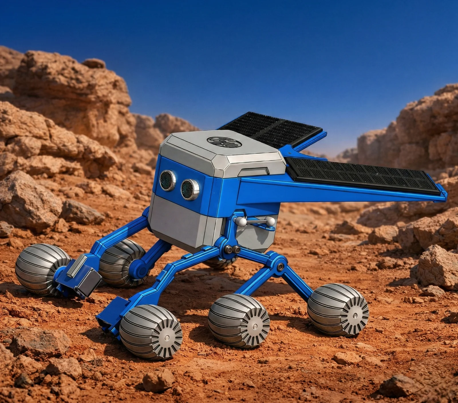
Introducing Explorer Otto, a complete modification that transforms the friendly base we all know into an off-road exploration vehicle.
The main idea was to give Otto the ability to traverse complex obstacles. To achieve this, I developed and adapted:
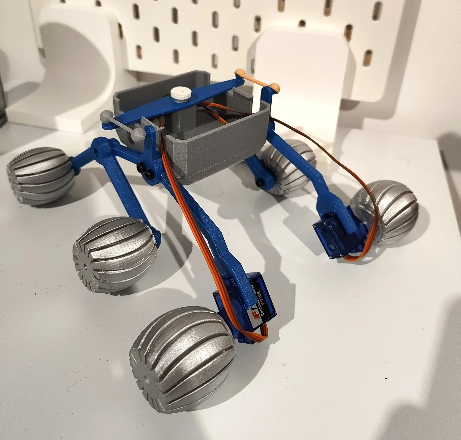
Rocker-Bogie System: I replaced the traditional legs with a mechanical suspension inspired by Martian rovers. This allows Otto to keep all wheels in contact with the ground while climbing rocks and uneven terrain.
Solar Panel Mount: Every good space explorer needs energy, so I designed a dual rear mount to accommodate two solar panels (1W, 11x6cm), giving it that futuristic and functional “long-duration mission” look.
It was a challenge to design a fully 3D-printed rocker-bogie system. In my tests, it worked well, but you should follow a few important tips. 🔧🚀
I recommend printing the system in PETG or ABS. All parts were designed to be printed without supports.
The rocker is the large component of the rocker-bogie system. I designed it to use the same motors from the original Otto kit, but in this version we need to place the motor on the outside of the robot. Therefore, I added small tabs that help guide the servo cables toward the holes located at the bottom of the bottom piece.
The remaining wheels attached to the bogie are not motorized; they rotate freely.
You must install heat inserts at the following points:
2× Rocker–pivot joint. You may also try using self-locking screws here.
On each rocker, at the joint connection with the bogie, use 10 mm screws here. Tighten them fully — you should still be able to rotate the joint normally afterward.
Inside the bottom piece is where the magic happens. You should position the two rockers in the cylindrical cavities and secure the locker on top with self-locking screws. Since this is where most of the friction occurs, it might be a good idea to apply some lubricant, even though I didn’t use any in my assembly.
In my tests, for the free-spinning wheels, I installed a heat insert inside each wheel and used a 10 mm M3 screw. Just like in the other joint, you can tighten it all the way — there’s still enough play to allow the wheel to rotate freely.
Another possible option is to place the heat insert in the bogie and use a longer screw that passes through the entire wheel.
For the motorized wheels, note that there is a separate file for them. You should use the mounting holes to attach the circular plastic servo adapter that comes with the motor.
You can experiment with different materials for these wheels. I tested them with 90A hardness TPU and was happy with the results. PETG also works, but keep in mind that the grip on rocks will be slightly compromised.
Have Fun!
Byadvanced-hobby-labLikes0Downloads290

 ByleonicLikes0Downloads1.4K

 ByZED4EverLikes313Downloads5.2K

 ByfifindrLikes500Downloads4K

 ByVC_DesignLikes679Downloads3.6K

 ByDan Schwartz SchwartzLikes744Downloads3.4K

 Byvc-designLikes0Downloads3.2K

 ByUpcrid3D_1585693Likes808Downloads2.1K

 ByWilko_SLOLikes935Downloads2K

 ByshoheiyLikes0Downloads426

 Bychubbs8697_2027893Likes585Downloads1.7K

 Byquibeck_3353173Likes965Downloads1.9K