



Kẹp giữ sợi Filament
 Bytinx_1344834Likes1.2KDownloads6K
Remix of Thanh đèn LED gắn hông máy in Prusa i3 MK3 By In3DSpace
Build another version of this model.
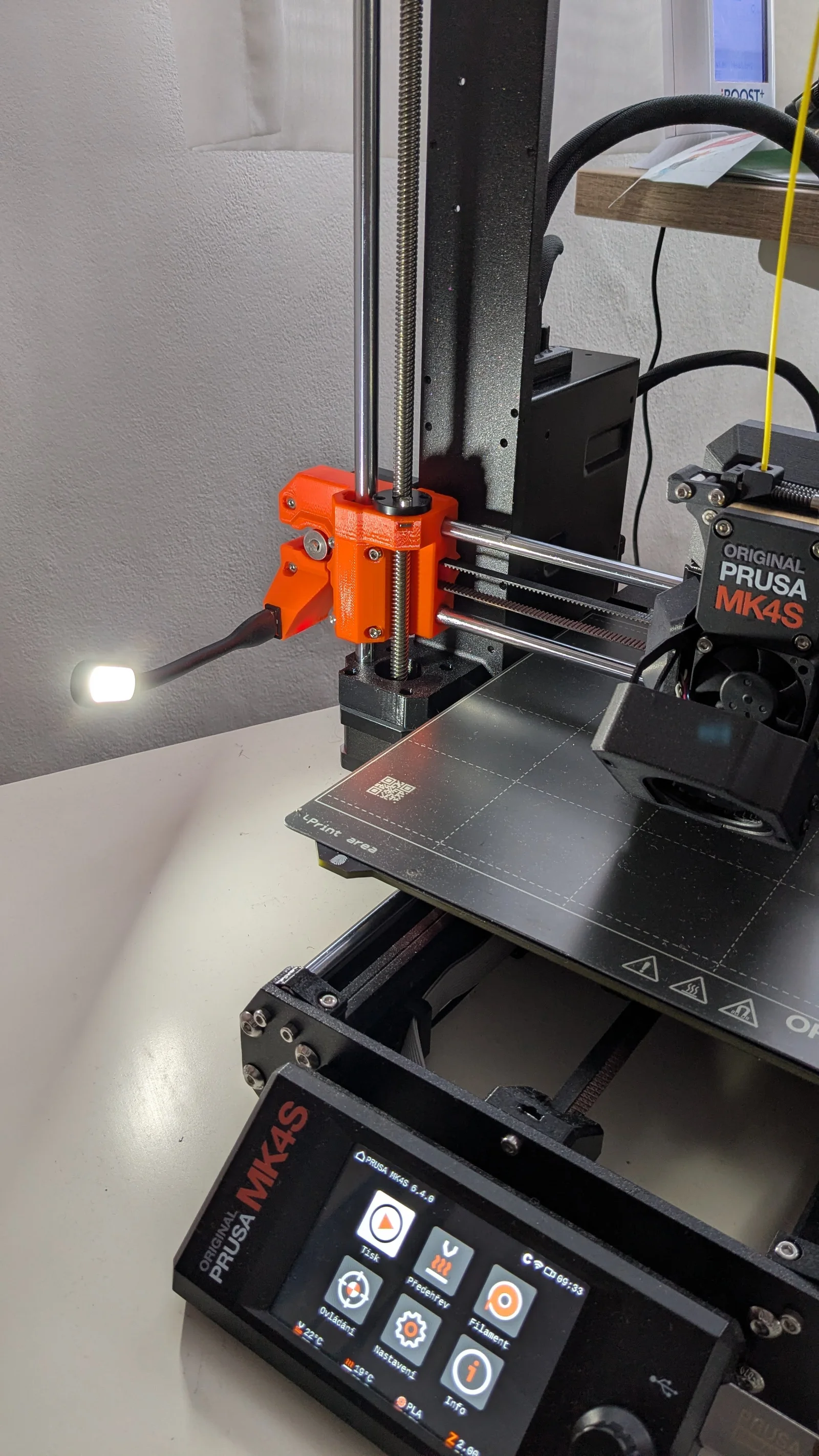
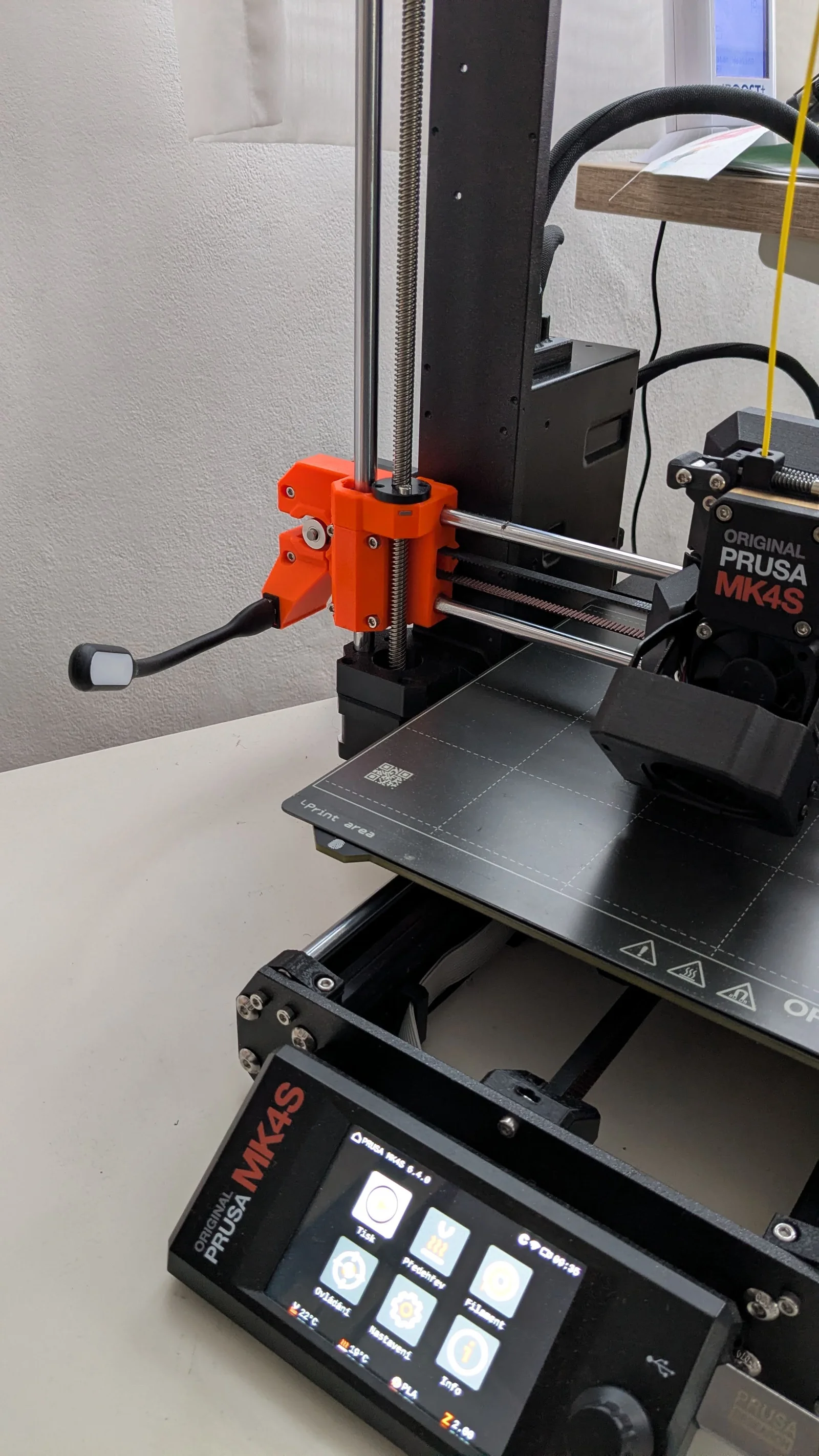
USB (type A) powered side LED lamp for Prusa MK4/MK4S. Attaches to the X-axis motor. Wire routes out the back and through the X-axis motor wire sleeve into the electronics box. Includes an opening for a power switch.
Most of the lamps I've seen attach to the top frame, which casts shadows onto the plate through the extruder. Not so with this side lamp! Moreover, the lamp is bendable, so you can adjust its position.
Recommended Print Settings
No supports needed
Lay it on the back and make a horizontal cut 10mm above the plate
Add 2 plug-type connectors 1.5mm in diameter
Enable a fuzzy skin (0.1mm thickness) on the ouside walls except for the connectors - this imitates the look of the original orange Prusa parts
To make the USB socket frame a different color, change it for the top 5 layers
Open 3MF file in PrusaSlicer for preconfigured settings
Required Hardware
USB DC buck step down converter 24V->5V
10 Ohm resistor or similar
22 AWG Wire
Power switch (KCD11 10x15mm)
5V USB LED reading lamp of your choice max. 10Watts (2A) of continuous load (see the USB converter specs. for details)
Screw M3x18mm Cap Head Screw
Heat shrink tubing
2 Ring (or fork) terminals
Tools
2.5mm Hex key
Soldering station
Assembly Instructions
Take the switch, resistor and USB converter and solder them one by one in series. Use the USB converter (+) pin. I would recommend not inter-connecting them with wires after all since there is very little space inside the printout. Use the heat shrink tubing to avoid short circuit.
Cut approx. 55cm of the wire. Connect the red wire (+) to the switch and the black wire (-) to the USB converter (-)
Put the back side of the printout on the wire and close it. Use the M3x18 screw to attach it to the x-axis motor.
Put on the heat shrink tubing and solder the ring terminals to the other side of the wire.
Switch off the printer!
Open the printer electronics box, loosen the screws on the top wire holder and pass the wire in from the top.
Unscrew the Power cables and add the rings under the screws respecting the polarity! Your red wire goes under the (+) screw and your black wire under the (-) screw. Close the printer electronics box.
Wrap the wire inside the X-axis motor sleeve.
You're done. Now is the time to test. Plug in your USB lamp and turn the printer on. Test the switch.
Bytinx_1344834Likes1.2KDownloads6K

 ByltloweLikes26Downloads126

 Byprusa-researchLikes0Downloads2.7K

 Bydet-manLikes0Downloads179

 Bygummiegecko8477Likes0Downloads171

 Bychukwufumnanya-arinzechukwuLikes0Downloads155

 Bychris-barwickLikes0Downloads134

 BydalleLikes0Downloads153


 BynasikLikes0Downloads125

 Byarhi_585078Likes64Downloads547

 ByPengLordLikes32Downloads116