

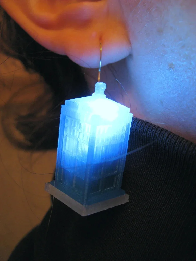
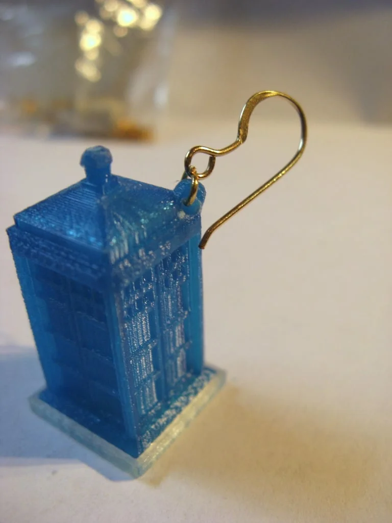


Đôi cánh Hermes, sứ giả của các vị thần
 ByOldLadyLikes876Downloads2K
Build another version of this model.
Optional assembly to enable lighting. Has successfully been printed in ABS and PLA via Flashforge Creator and Makerbot 1 printers.
Choice of file sets to print:
1 TARDIS
1 Bottom plug - for the LED option
or
2 TARDIS
2 Bottom plugs - for the LED option
3D Printing (Successful Makerware Settings):
High (detail / fine quality)
Infill 15%
Number of Shells 3
Layer Height 0.1 mm
Extrusion Temp 230C
Extrusion Speed 80
Assembly Materials (for one earring)
NOTE: the LED burns through the batteries because there is no resistance. I suggest adding a resistor somehow. These instructions are how I originally assembled my earring set.
TARDIS and Plug STL files
LED - 3volt
3x 1.5volt LR41 Button Batteries
Masking tape (non-electrically conductive tape)
Earring hoop
Jewelry jump hoop
Assembly Tools
1/16th drill
Needle-nose pliers
Wire cutters
Earring Assembly Directions
Print TARDIS (use the pair files if want a pair)
Drill using the 1/16th drill to put a hole at the base of the nub on the top of the TARDIS (pictured). This is probably best done via hand and not a powered drill.
Insert a jump ring into the nub hole and the earring hoop. Use the pliers to close the loop.
Light-up Earring Assembly Directions
Print the plug (use the pair files if want a pair) - this can be performed with Step 1 of the Earring Assembly.
Tape the button cells into a column leaving the top and bottom clear of tape. Make sure that the batteries all have the same orientation (ie positive to negative connections).
Bend the LED wires into the configuration pictured. The longer end of the LED wire is the positive and needs to make contact with the top of the battery column (the smooth top of the battery). You will likely need to cut down this wire to length. I also recommend taping the LED lead to the battery column. Leave the bottom wire such that it is NOT actively in contact with the battery column but that when pressed up from below, forces the wire to connect with the battery column and completes the electrical loop.
Insert the taped LED/battery sub-assembly into the TARDIS with the LED at the top.
Snap on plug piece to turn assembly on (this forces the bottom wire to make contact with the bottom of the battery column, completing the electrical loop). Likely will require pressure to snap the plug into place.
ByOldLadyLikes876Downloads2K

 ByremingtonLikes162Downloads557

 ByDevis_1367119Likes416Downloads2K

 ByFC2M3DLikes200Downloads1.3K

 ByVinors3DLabLikes949Downloads2.1K

 ByGQincLikes77Downloads137

 ByviewoyLikes0Downloads255

 By2viewsLikes391Downloads389

 Byms-d3signLikes0Downloads210


 ByvanessaLikes0Downloads120

 ByNorkkon_252760Likes76Downloads211