



New
AAA Battery Case
 Bylab-96Likes0Downloads106
Build another version of this model.
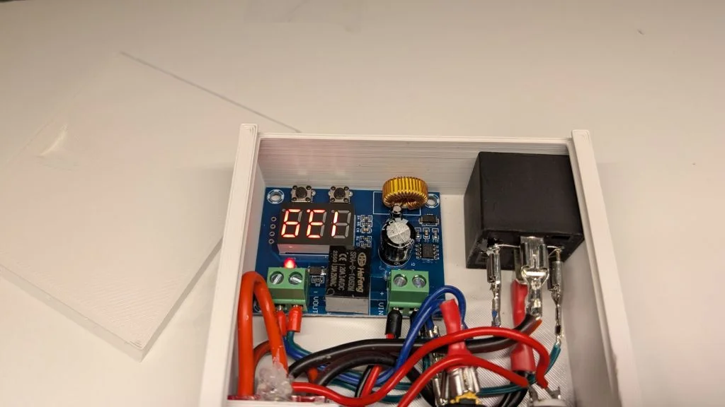
The model is a box with sliding lid built to house a fuse protected, low voltage disconnect module driving a 40 amp automotive relay and using anderson powerpole connectors for power input and output. I built this for use with my LifePO4 batteries when powering a Starlink Mini and/or mobile radios.
The XH-M609 module can be used as a low voltage disconnect to help protect a battery from excessive drain. The problems with using the module include small lines for the input and output lines as well as use of a lightweight relay. It also continues to present a load on the battery even after opening the relay, which can itself contribute to over discharge of the battery.
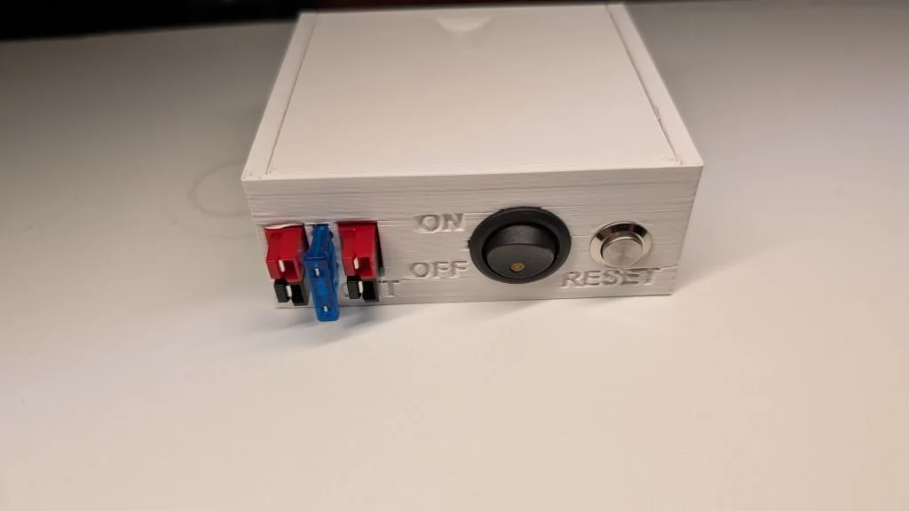
This model is built to help address those shortcomings using an illuminated rocker switch, a momentary pushbutton switch and a 40 amp automotive relay configuration to create a latching relay. When the low voltage disconnect occurs, and the automotive relay opens, the board is disconnected from the battery power feed and no longer represents any drain on the battery. Anderson powerpole connectors are used for convenience and a fuse mount provides for circuit protection.
The XH-M609 module input is tied to the power input ground and the automotive relay output terminal +. The relay solenoid is itself powered by the XH-M609 module Vout terminals, mediated by the rocker switch on the + line. The power input + line runs through the fuse and then connects to the automotive relay input + terminal. The momentary push button provides a momentary connection between the XH-M609 Vin + terminal and the power input +. Once the XH-M609 is activated the Vout lines activate the automotive relay (if the rocker switch is in the "on" position. Power input - line has connections to both the XH-M609 Vin - input and the illuminated rocker switch ground terminal.
The box opening for the illuminated rocker switch is sized for a 20mm round switch. Like this one. www.amazon.com/dp/B07T1JG6BD The box opening for the momentary push button is sized for a 12mm round switch. Like this one. www.amazon.com/dp/B0811QKG1R
The anderson powerpole connector openings are sized for a pair of connectors and they "snap" into position with a rib on the opening fitting into a recess on the connector. Fit the black connector first, when follow with the red connector in the configuration shown in the pictures ("red on right, tongues up").
The fuse connector consists of two 1/4" female spade quick connect crimp fittings. Attach the wires and then insert the assembly from the front. Once both are in place, a blob of hot glue (or equivalent) will help prevent pull out when the fuse is removed.
The XH-M609 board and relay are secured in place with VHB, servo tape, or equivalent.
Once assembled, with the lid removed, connect input power and start the board by setting the rocker switch to the "on" position and pressing the momentary push button. That should illuminate the board voltage display and close it's on-board relay, illuminating a red LED indicator. Per the instructions provided with the board, set your desired low voltage cutoff value and "difference" value to enable restart. Depending on the version, you may also have the option to calibrate the voltage display.
Normal operation should consist of connecting feeds from battery & load, setting the rocker switch to the "on" position, then pressing the momentary pushbutton. You shold hear the relay "click" and see the rocker switch LED illuminate.
Some XH-M609 boards include the option for a "cool down" timer that creates a delay before the board relay closes on initial powerup. If available, the default value should be "0". If not, then the pushbutton would have to be held for the delay period before the relay trips. Setting that delay to "0" will remove any wait time.
Fusion 360 source and .STEP files are provided as well as .STL files. I suggest using tree supports from the build surface. I printed in ASA for temperature and UV stability.
Bylab-96Likes0Downloads106

 ByrjunLikes0Downloads304

 ByleonicLikes0Downloads1.4K

 ByZED4EverLikes313Downloads5.2K

 ByVC_DesignLikes271Downloads756

 ByfifindrLikes500Downloads4K

 Bymrfixit_324954Likes65Downloads478

 ByDan Schwartz SchwartzLikes744Downloads3.4K

 ByBrokentooth_designsLikes83Downloads453

 Byvc-designLikes0Downloads3.2K

 Bythorin-oakenshieldLikes0Downloads531

 Bytorii-creative-studioLikes0Downloads449