



Bộ sưu tập 11 nhân vật mô hình Mecca Chameleon in 3D vui nhộn
 ByZED4EverLikes313Downloads5.2K
Build another version of this model.
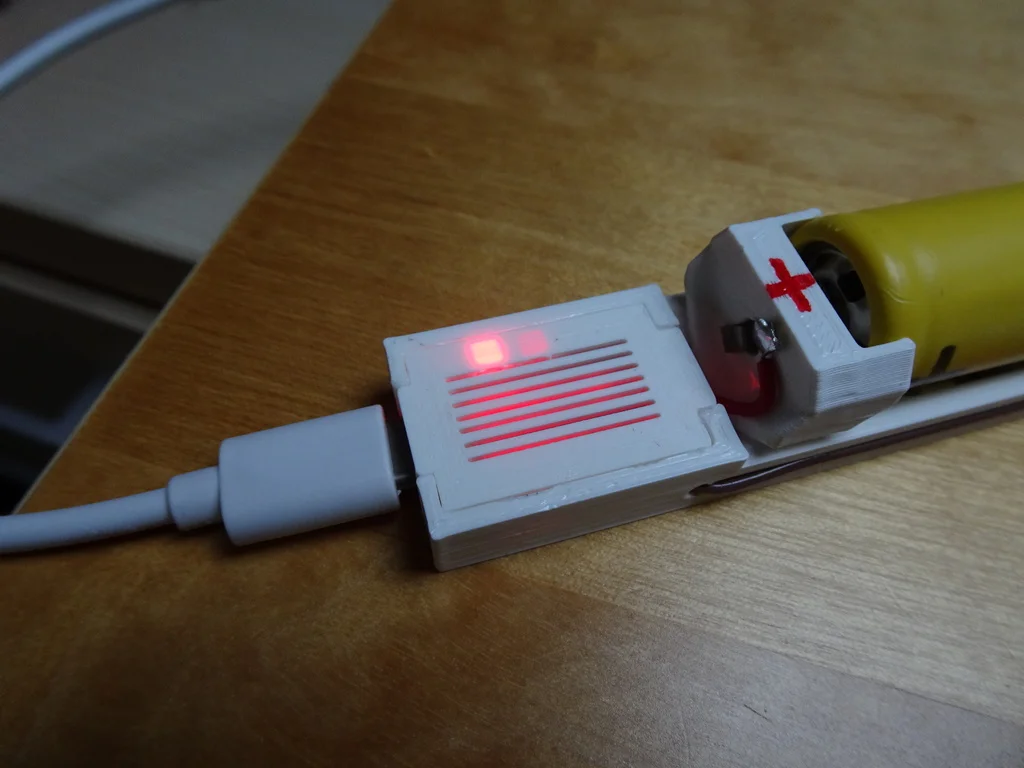
Yet another charger housing. I found several similar things here, most are made to fit the (old?) PCB layout of the TP4056. Found few for the new PCB, but didn't really like the unprotected PCB and other detail.
Now this is to be used with the new layout TP4056 PCB (easy to recognize with the two small tabs on the PCB opposite side of the USB socket, see the model by Robin https://www.thingiverse.com/thing:3626660).
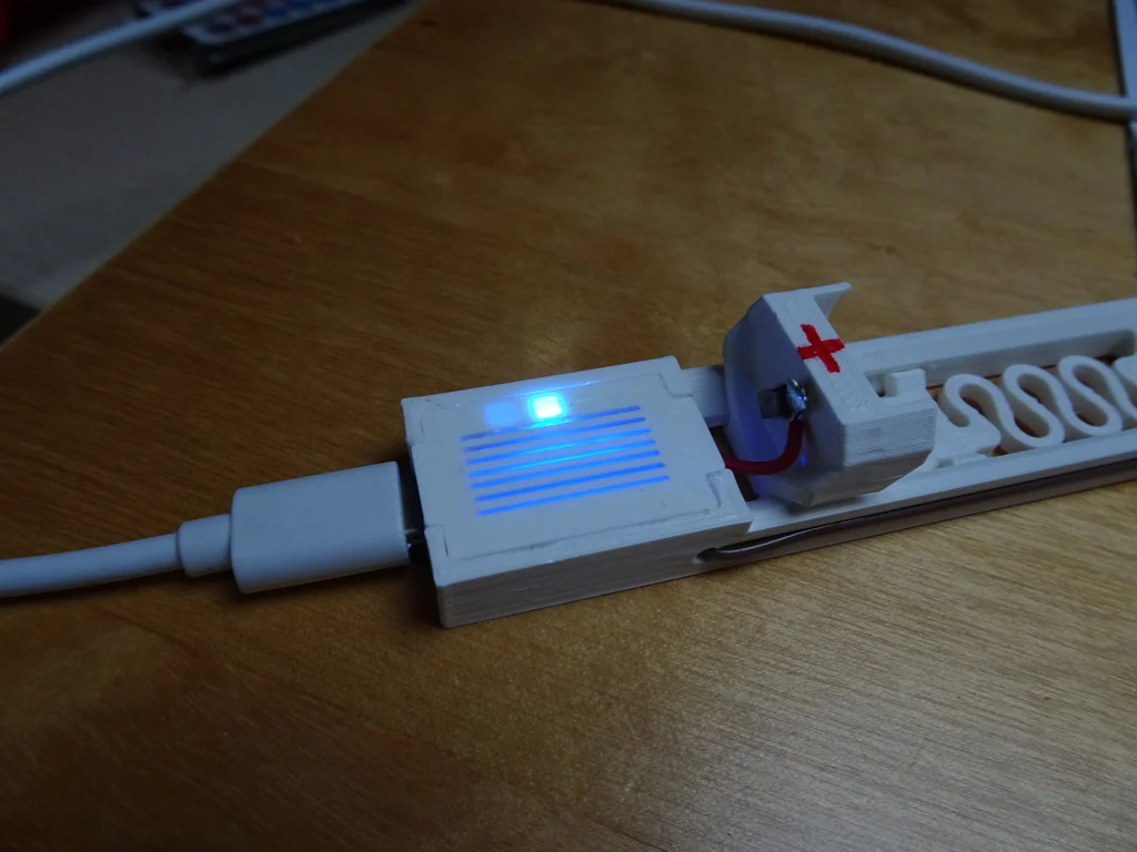
I used the famous https://www.thingiverse.com/thing:2668159 as battery holder. Alex' design is for me by far the best, the integrated pull-spring works very good, and with a well calibrated printer it works right of the print bed.
The cover plate should snap in, if it does fit to loose, use some CA glue to secure it.If it can't be pushed in, trim it with a sharp knife.
The cover has a small very thin section to allow PCB LEDs to shine through, these are very bright in general on these PCBs.
Printer Brand:
Creality
Printer:
CR-6 SE
Rafts:
No
Supports:
No
Resolution:
0.2
Infill:
50%
Filament: Quality stuff! There are HUGE differences in strength PLA, PETG
Notes:
Give it at least 50% infill to strengthen the movable part. NO SUPPORT needed!
Post-Printing =============
Assembly, soldering instructions
As contacts I used "Musterklammern", see pictures here: https://de.wikipedia.org/wiki/Musterklammer
First solder wires to the PCB, determine length (negative wire can be glued into the small notch on one side of the holder - see attached Tinkercad-screenshot)
Insert the PCB into the holder, make sure the two small tabs enter the holes facing the battery side, and the USB socket fits into the groove on the other side. (see attached Tinkercad-screenshot)
Tin- coat the "Musterklammer" before installing with your soldering iron, to keep actual soldering to the wire short for not melting the PLA thing.
Put "Musterklammern" through the holes, solder wires to them, push cover plate into place (the side with the longer tab goes over the USB-socket).
here you are.
Modified the source objects and added parts in Tinkercad
Category: Electronics
ByZED4EverLikes313Downloads5.2K

 ByrjunLikes0Downloads300

 ByAdam Záhořák ZáhořákLikes39Downloads259

 ByleonicLikes0Downloads1.4K

 ByVC_DesignLikes271Downloads755

 ByfifindrLikes500Downloads4K

 Bymrfixit_324954Likes65Downloads476

 Bylab-96Likes0Downloads104

 ByDan Schwartz SchwartzLikes744Downloads3.4K

 ByBrokentooth_designsLikes83Downloads451

 Byvc-designLikes0Downloads3.2K

 Bythorin-oakenshieldLikes0Downloads529