



Bộ sưu tập 11 nhân vật mô hình Mecca Chameleon in 3D vui nhộn
 ByZED4EverLikes313Downloads5.2K
Build another version of this model.
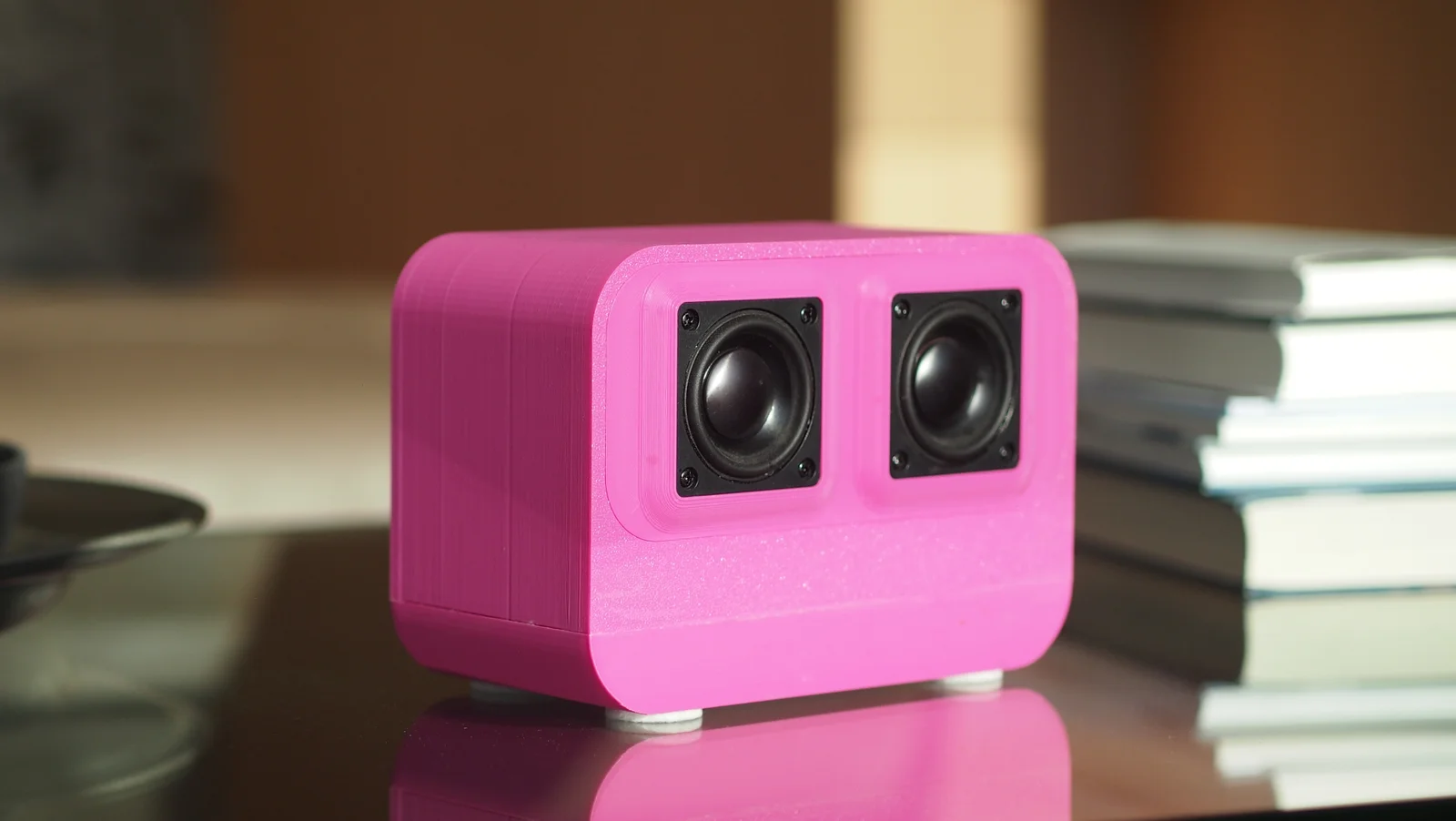
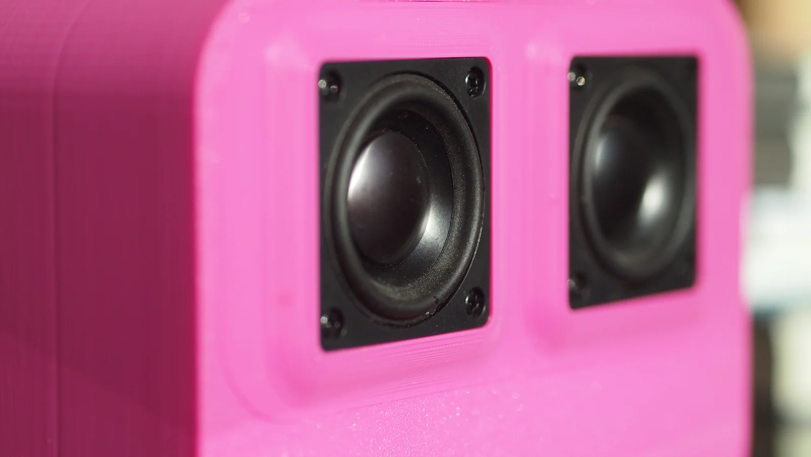
CORE- a 3D-Printed Bluetooth Speaker with Dual Drivers
This compact speaker uses two Dayton Audio DMA58-4 full-range drivers to deliver surprisingly powerful and clear sound from a very small enclosure. The fully 3D-printed housing includes a bass-reflex system for deeper low-end, while the internal amplifier and battery setup make it completely portable. Despite its size, the speaker offers punchy bass, clean mids, and crisp highs — perfect for everyday listening on the go.
BOM:
2x Dayton Audio DMA 58-4
Order Dayton Audio DMA58-4 Full-range Woofer - SoundImports
Sure Electronics 3S 18650 BCPB2 Batteryboard
Dayton Audio KAB-215v2 2x15W Amplifier
Order Dayton Audio KAB-215v2 Amplifier module - SoundImports
3x High Quality 18650 Batteries
Samsung, Sony, etc.
16x M3x12mm self-tapping screw
~60cm cable (must handle 30W, so doesn't need to be thick)
Order Red/black speaker wire - SoundImports
rocker switch 15x21mm
5/20/100Pcs 2Pins KCD1 Electrical Power Boat Shape SPST ON-OFF KCD11 Rocker Switch Toggle Switch
Red 3mm LED
680 Ω resistor
JST-PH Plug with wires
5.5x2.1mm DC 099 Power Jack
Total: ~120€
Assembly Guide
1. Screw both drivers into the front plate.
2. Solder ~20 cm wires to each driver (watch polarity and phase!).
3. Route the wires through the cable holes in each of the two-piece enclosure.
4. Glue the front plate into the body using plenty of glue so the joint is fully airtight.
5. Seal the cable pass-through holes with glue for air tightness.
6. Glue the two printed bass-reflex ports into the back plate (again: airtight).
7. Glue the back plate onto the enclosure — seal it properly.
8. Put in the batteries in the battery board. Then Screw the amplifier board and battery board onto the mount.
• Battery board = long spacers
• Amplifier board = short spacers
9. Solder speaker wires to the amp output
• L+ → left speaker +
• L– → left speaker –
• Same for right channel
10. Glue the red 3 mm charging LED into the Bottom part, add a 680 Ω resistor in series, then solder a 2-pin JST-PH plug (check polarity) and plug it in to the externel charging LED Port on the battery board (J2).
11. Press the power switch into the Bottom part.
12. Connect battery board output (J11) → amplifier input, with the switch in between.
13. Press in the charging port in the Bottom part and screw it in place. Then connect the charging port to the battery board Wago J4 input (correct polarity!).
14. Glue the Bottom part to the main body (airtight).
15. Charge it up and enjoy the music
Picture is from the official Sure Electronics Batteryboard PDF
ByZED4EverLikes313Downloads5.2K

 ByfifindrLikes500Downloads4K

 ByVC_DesignLikes679Downloads3.6K

 ByDan Schwartz SchwartzLikes744Downloads3.4K

 Byvc-designLikes0Downloads3.2K

 ByUpcrid3D_1585693Likes808Downloads2.1K

 ByWilko_SLOLikes935Downloads2K

 Bychubbs8697_2027893Likes585Downloads1.7K

 Byquibeck_3353173Likes965Downloads1.9K

 BySeppoTakaloLikes960Downloads1.9K

 ByRobertoGalloc_356815Likes549Downloads1.8K

 ByTater_364200Likes486Downloads1.6K