



Marci's Mount - Ngàm in 3D cho kính thiên văn Hadley
 ByMarciLikes87Downloads296
Build another version of this model.
English description below
OnStep-Umbau für die Vixen New Polaris Montierung
Für das großartige OnStep-Projekt von Howard Dutton https://onstep.groups.io/g/main
Hier handelt es sich um eine Adaption für eine Vixen New-Polaris Montierung aus den 1980er-Jahren.
Dies ist kein Projekt für Einsteigerinnen oder Einsteiger. Solide Kenntnisse im Löten und Crimpen von Kabeln werden vorausgesetzt.
Alle grundlegenden Informationen zum Aufbau und zur Konfiguration einer OnStep-Steuerung finden sich im offiziellen OnStep-Wiki: https://onstep.groups.io/g/main/wiki/32747
Es stehen keine CAD-Dateien zur Verfügung, da alle Modelle direkt in TinkerCAD erstellt wurden.
Gehäuse für OnStep
Gehäuse für die OnStep-Steuerung (Fysetc E4):
https://www.printables.com/model/1516567-onstep-fysetc-e4-enclosure
Gehäuse für das Handcontroller-Modul SHC-2:
https://www.printables.com/model/1516487-onstep-shc-2-enclosure
RA-Motorhalterung
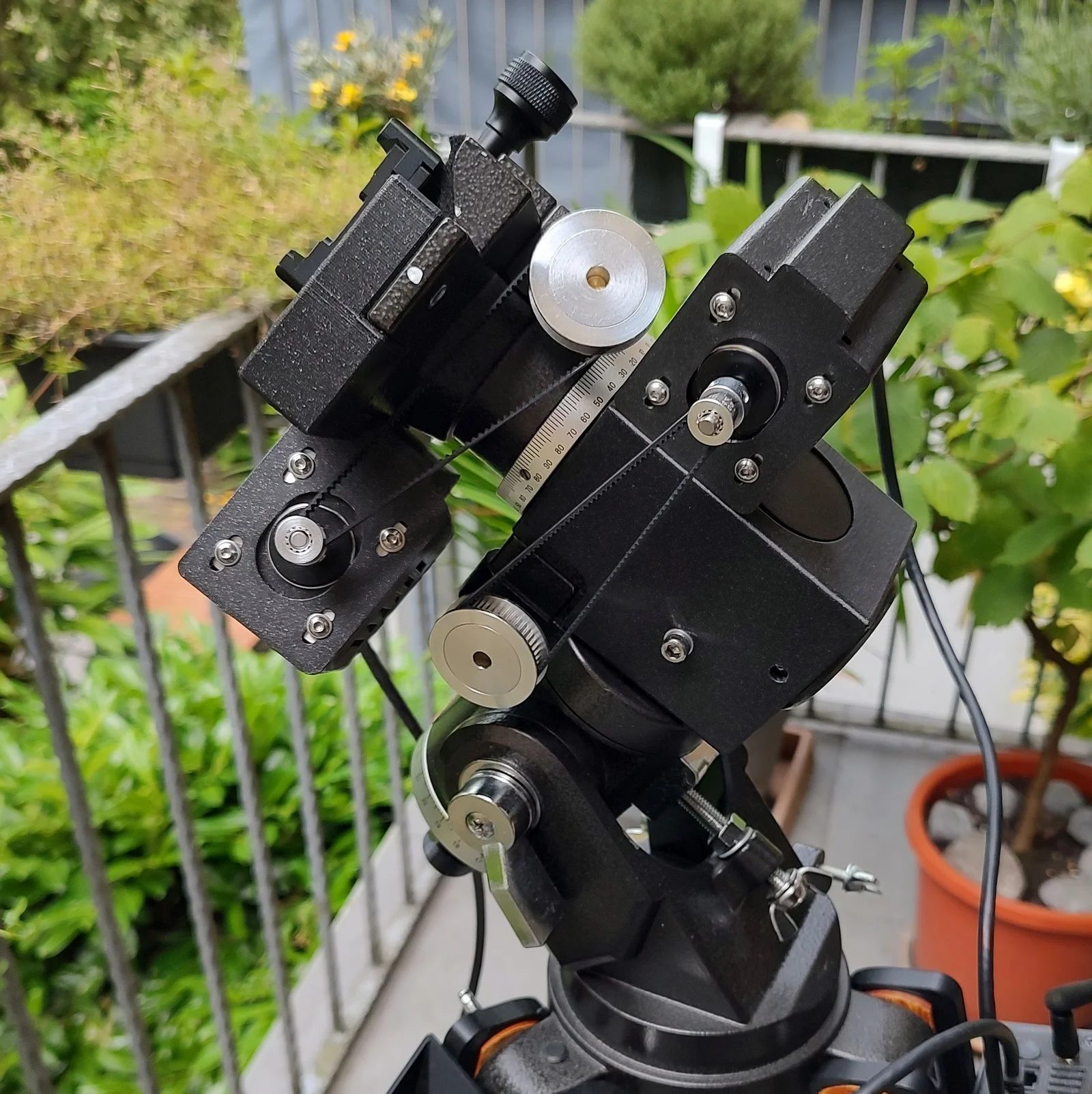
Die New-Polaris-Montierung hat keine Befestigungspunkte für Motore. Daher wurden auf die Montierung zu setzende Halterungen konstruiert.
Die RA-Motorhalterung besteht aus einem Aufsatz für den Hauptkörper der Montierung. Um diese zu befestigen muss die Scheibe mit dem Gewinde für das Gegengewicht aus der Montierung herausgeschraubt werden (Inbus-Sicherungsschrauben an der Seite!).
Der Aufsatz wird nun auf die Montierung aufgesetzt und mit einer M4-Schraube von der Seite und der wieder einsetzten Scheibe mit den Gegengewichstgewinde an der Montierung befestigt.
Die Motorhalterung wird mit 4 Senkkopfschrauben und entsprechenden Einpressgewinden mit der Halterung verschraubt.
DEC-Motorhalterung
Zur Befestigung der DEC-Motorhalterung wird die Teleskop-Halterung durch einen Aufbau ergänzt. Zur Befestigung von leichten Optiken (mehr trägt die New-Poalris nicht) ist dort eine Arca-Swiss-Klemme vorgesehen.
An dieser Halterung wird die DEC-Motorhalterung mit Hilfe von drei M3-Schrauben und entsprechenden Einpressgewinden befestigt.
Abdeckungen der Motorhalterungen
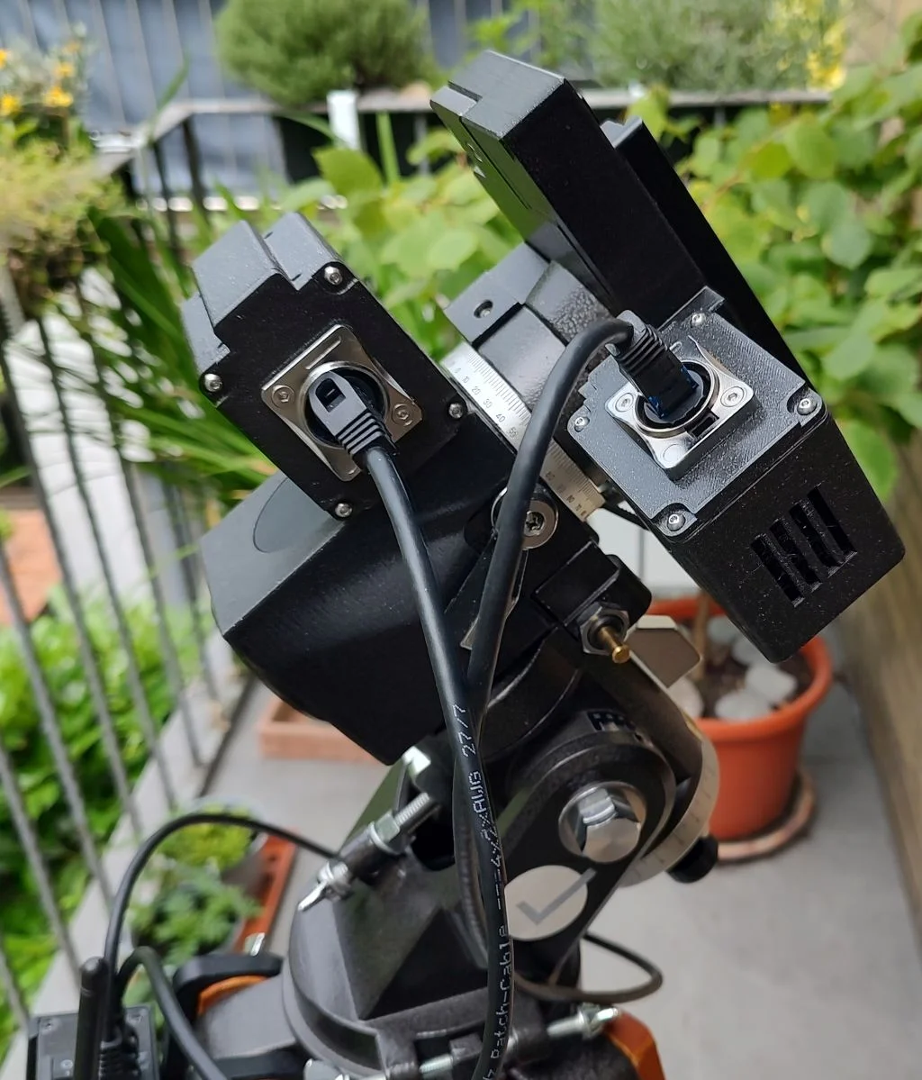
Die Abdeckungen der Motorhalterungen werden mit M2,5-Schrauben und in die Halterungen eingeschmolzenen Gewindeeinsätzen befestigt. Die Abdeckungen gibt es für GX12 Einbaubuchsen (m) oder RJ45-Buchsen.
Freigängigkeit und Übersetzung
Gegebenenfalls müssen die Positionen der Klemmhebel für RA und DEC angepasst werden, da die großen Zahnriemenscheiben sehr knapp daran vorbeilaufen.
Die Untersetzungen der Newpolaris-Montierung sind in der RA-Achse 144:1, in der DEC-Achse 72:1. Eine Beispiel-Kalkulation für OnStep ist bei den Bildern zu finden.
Optinale Polsucher-Abdeckung
Die Polsucher Öffnung wird mit einer Kappe aus TPU (Flex) verschlossen, die etwas schwierig einzusetzten oder zu öffnmen ist.
Für Montierungen ohne Polsucher kann das Fadenkreuz eingesetzt, dass eine ungefähre Polausrichtung erlaubt.
Benötigtes Material
2 × NEMA-17-Schrittmotore
2 × GX12-Einbaustecker
oder RJ45 Einbaubuchsen
2 x M8×16-Schraube mit Unterlegscheibe (Ø 16 mm)
M5×10-Schraube mit Unterlegscheibe
2 × Zahnriemenscheiben mit 48 Zähnen
2 × Zahnriemenscheiben mit 12 Zähnen
→ ergibt eine Übersetzung von 4:1
GT2-Zahnriemen, 6 mm breit, 142 Zähne (284 mm) - RA
GT2-Zahnriemen, 6 mm breit, 132 Zähne (264 mm) - DEC
Arca-Swiss Klemme 120mm und zwei 1/4" Foto-Schrauben
Gewindeeinsätze zum Einschmelzen: M3 und M2,5
M3-Senkkopfschrauben
M2,5-Linsenkopfschrauben
Druckempfehlungen
Material: PLA oder PETG (bei Einsatz in der Sonne empfohlen) - Ich verwende PLA, da es steifer ist.
Düse: 0,4 mm
Schichthöhe: 0,2mm
Perimeter: 3 (weniger Perimeter können Probleme beim Einsetzen der Gewindeeinsätze verursachen)
Infill: Gyroid, 15 %
Stützstrukturen: siehe Bilder
Drucker: FDM – die Teile wurden auf einem Prusa MK4S gedruckt
Translation by ChatGPT
OnStep Conversion for the Vixen New Polaris Mount
For the excellent OnStep project by Howard Dutton: https://onstep.groups.io/g/main
This is an adaptation for a Vixen New Polaris mount from the 1980s.
This is not a beginner project. Solid skills in soldering and crimping cables are required.
All basic information on building and configuring an OnStep controller can be found in the official OnStep Wiki: https://onstep.groups.io/g/main/wiki/32747
No CAD files are available, as all models were created directly in TinkerCAD.
Enclosures for OnStep
Enclosure for the OnStep controller (Fysetc E4):
https://www.printables.com/model/1516567-onstep-fysetc-e4-enclosure
Enclosure for the SHC-2 hand controller module:
https://www.printables.com/model/1516487-onstep-shc-2-enclosure
RA Motor Mount
The New Polaris mount has no built-in mounting points for motors. Therefore, clamp-on mounts were designed that are attached directly to the mount.
The RA motor mount consists of an attachment for the main body of the mount. To install it, the disc with the counterweight shaft thread must be unscrewed from the mount (Allen locking screws on the side!).
The attachment is then placed onto the mount and secured using an M4 screw from the side and the reinstalled disc with the counterweight thread.
The motor bracket is fastened to the attachment using four countersunk screws and corresponding press-in threaded inserts.
DEC Motor Mount
To attach the DEC motor mount, the telescope saddle is extended with an additional structure. For mounting lightweight optics (the New Polaris cannot carry more), an Arca-Swiss clamp is provided at this location.
The DEC motor mount is attached to this bracket using three M3 screws and corresponding press-in threaded inserts.
Motor Mount Covers
The motor mount covers are fastened with M2.5 screws and heat-set threaded inserts embedded in the mounts. The covers are available for GX12 panel-mount connectors (male) or RJ45 sockets.
Clearance and Gear Ratio
If necessary, the positions of the RA and DEC locking levers must be adjusted, as the large timing pulleys pass very close to them.
The reduction ratios of the New Polaris mount are 144:1 on the RA axis and 72:1 on the DEC axis.
An example calculation for OnStep can be found in the images.
Optional Polar Scope Cover
The polar scope opening is closed with a TPU (flex) cap, which is somewhat difficult to insert or remove.
For mounts without a polar scope, a reticle can be installed that allows for an approximate polar alignment.
Required Materials
2 × NEMA 17 stepper motors
2 × GX12 panel-mount connectors
or RJ45 panel-mount sockets
2 × M8×16 screws with washers (Ø 16 mm)
M5×10 screw with washer
2 × timing pulleys with 48 teeth
2 × timing pulleys with 12 teeth
→ results in a 4:1 gear ratio
GT2 timing belt, 6 mm wide, 142 teeth (284 mm) - RA
GT2 timing belt, 6 mm wide, 132 teeth (264 mm) - DEC
Arca-Swiss clamp, 120 mm, and two 1/4" camera screws
Heat-set threaded inserts: M3 and M2.5
M3 countersunk screws
M2.5 pan-head screws
Printing Recommendations
Material: PLA or PETG (recommended for use in sunlight) – I use PLA because it is stiffer
Nozzle: 0.4 mm
Layer height: 0.2 mm
Perimeters: 3 (fewer perimeters may cause problems when inserting the threaded inserts)
Infill: Gyroid, 15%
Supports: see images
Printer: FDM – the parts were printed on a Prusa MK4S
ByMarciLikes87Downloads296

 By_3883847Likes2Downloads10

 Bystrifu_4061046Likes151Downloads1.3K

 ByBoonby_1059917Likes659Downloads1.2K

 ByDMUX_214162Likes0Downloads15


 ByFatesEndLikes1Downloads9

 ByFabianVeileLikes414Downloads1.5K

 BygillisLikes121Downloads2.1K

 BynleinadLikes56Downloads185

 ByLat0102_256421Likes35Downloads139

 ByXypris_1659795Likes1Downloads7