



Ốp lưng cho Samsung S22 Ultra
 ByckthLikes148Downloads2.4K
Build another version of this model.
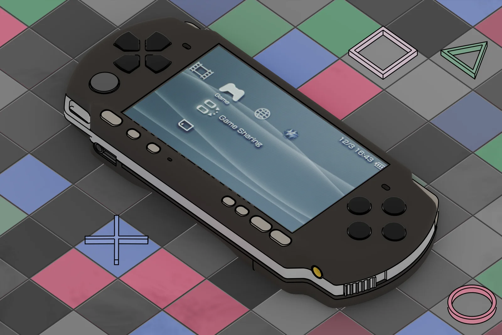
A complete, standalone shell kit designed for the PSP 2000 and 3000 (Slim) models. This custom shell is not compatible with original factory shells and is intended for full replacement or modding projects.
Current avaliable styles
Styles
Description
Default
The default design of the shell.
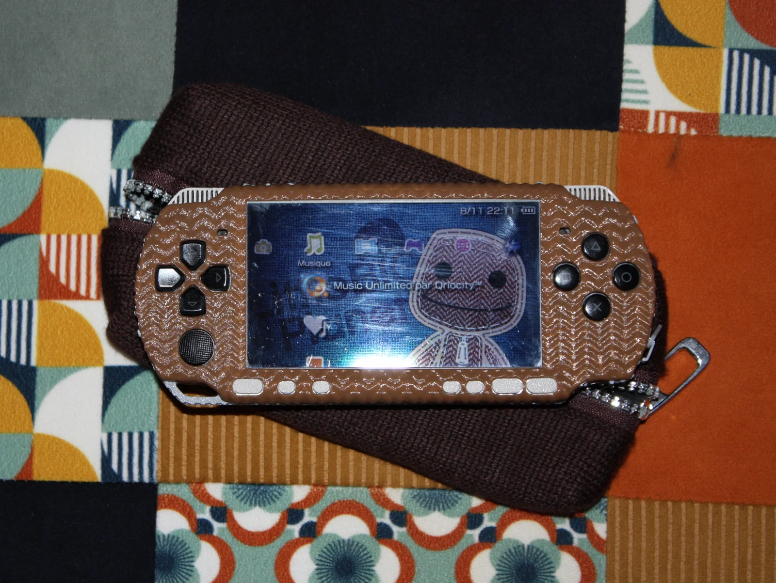
Sackboy / LittleBigPlanet
A Sackboy styled PSP with cardboard triggers + Zipper On/Off switch
Lemon
Thirsty ? Lemon lemon lemon
Some folders from different styles may have less files than the others, because they are direct replacements to the default style parts.
I will add other styles, if people have made custom styles, feel free to message me so that i put your printables link on the style table!
Features
Fat Battery Support – Includes space for the larger PSP 1000 battery (this means the slim battery isnt really supported)
Modding-Friendly Design – Extra space on the back for custom modifications (fans, heatsinks, etc.).
Compatible with 2000 & 3000 PSP models.
What You'll Print
Full Shell Assembly (front & back halves)
Internal & External Chassis Frames
All Buttons & Switches (media, Wi-Fi, power, face buttons, triggers)
Memory Card Door & Latch
3D printer capable of printing a minimum volume of 180mm x 180mm x 180mm.
Screwdriver appropriate for the screw sizes used (M3, small black PSP Screws).
Type
Components
Additional Information
Quantity (Recommended)
Plastic
PLA or better
To print all the parts
~200g
Screws
2x
Screws
2x
Screws
5x
Screen
Or plastic might also work
1x
PSP Parts
Metal threads
The ones used to screw accessories at the top
2x
PSP Parts
Small black screws
The ones holding the charging port, joystick and power button
3x
PSP Parts
The electronics
Everything except the UMD
1x
PSP Parts
Arrow buttons
1x
PSP Parts
Main buttons
1x
PSP Parts
Arrows conductive pad
1x
The right pad button might need to be modified if it doesnt fit properly
If you already have some M3x14mm or more you could try to cut them to the other sizes.
Printing is easy, the hard part is the post-processing of the face plate, be careful to not breaking it when removing the excess plastic, from experience, matte PLA broke easier in the corners of the screen repeatedly.
There is also the media buttons plate for the PSP 3000 wich is extremely fragile, i was able to print and put it in a PSP, but did break 3 - 5 before putting the mic, i will look for an alternative on how to make it.
The build guide is primarily designed for the PSP 2000, with additional notes for the PSP 3000 (which has minor differences). Once you’ve printed all parts (as listed above), you can begin assembly.
The point of view will change from time to time, so memorize the parts a bit so you dont get lost.
Make sure the shell chassis is flush with the frame, the 5 points clip into place.
🔵🔵The clips might a bit of strength to enter, be carefull to not break the parts.
Push the following pieces onto the chassis
🔵🔵 Only the memory card door and the accessories threads will hold into place, the other ones may fall, i recommend turning the frame's back upwards so they dont fall, it will also be necessary for the next step
Put the joystick onto the chassis and screw it in place
🔵🔵 For PSP 3000
I recommend connecting the joystick cable onto the motherboard and putting everything onto the frame in the next step.
Enter the motherboard and PSP sound/video module onto the case, they do fit but might be hard to put it correctly, make also sure that the Wi-Fi button lines up with the motherboard.
🔵🔵 For PSP 3000
This part will be easier than the PSP 2000 because the sound/video module is soldered to the motherboard, when pressing it down you will flex the frame a bit.
Glue the Wi-Fi antenna into place.
🔵🔵The cables may not be shown here, but you can already plug it onto the motherboard.
Put the speakers onto the following parts
🔵🔵They don't need to be glued, just pressed in, make sure the pins are a bit outwards to ensure contact with the motherboard and that they are flat and not angled.
🔵🔵Tip : Put the square side first into the piece at a slight angle and the press the other side into place.
Put the left button pad (Arrow side pad) onto the left piece. You can already glue it.
🔵🔵For the next steps, you dont need to glue the trigger buttons into the frame, they will stay there
Put the power/charging port into place and route the cables
Put the pieces on top of the frame
Screw 2 M3x4mm screws onto the top of the frame, don't overtighten them.
🔵🔵 Push the trigger button of the left membrane between the frame and the trigger, you don't need to glue it in place.
Screw the 3 M3x14mm from the back cover to the frame
Screw the charging port with a small black screw from the PSP.
Put the right membrane into place.
Put the power switch into place, make sure it lines up with the printed button.
🔵🔵 Push the trigger button of the right membrane between the frame and the trigger, you don't need to glue it in place.
🔵🔵 After screwing you can test it to check if the speakers, audio jack, charging port, etc work.
Glue the media buttons ribbon onto the printed media buttons plate.
🔵🔵 For PSP 3000
If you REALLY REALLY want to add the m
Plug in the media buttons
Plug the screen and put it in place
Secure the media button plate by putting in in the small rectangular holes on each side of the screen.
Glue the printed media buttons on the face plate, glue only the parts situated in the middle of the frame (from where the arrows are pointing).
Put the arrows on the face plate.
🔵🔵 You can also solder the
On this part you have 2 choices :
Glue the glass or plastic screen onto the face plate
Just put it on top of the screen
I recommend gluing it to the faceplate.
Put the bottom of the faceplate into the frame
Push down the top on the indicated part.
ByckthLikes148Downloads2.4K

 ByftoerringLikes79Downloads185

 ByFosphorLikes20Downloads238

 ByJaronLikes310Downloads1K

 Byw3rN42Likes127Downloads935

 ByjatinLikes0Downloads146

 ByDiscotehkLikes35Downloads154

 Byjodinskylab_3390035Likes144Downloads166

 ByfryseeLikes0Downloads144


 ByNoahLikes0Downloads203

 ByTomDDLikes89Downloads574