



New
Fortnite Pirate Shop Token
 Bylarp3dLikes0Downloads1.4K
Build another version of this model.
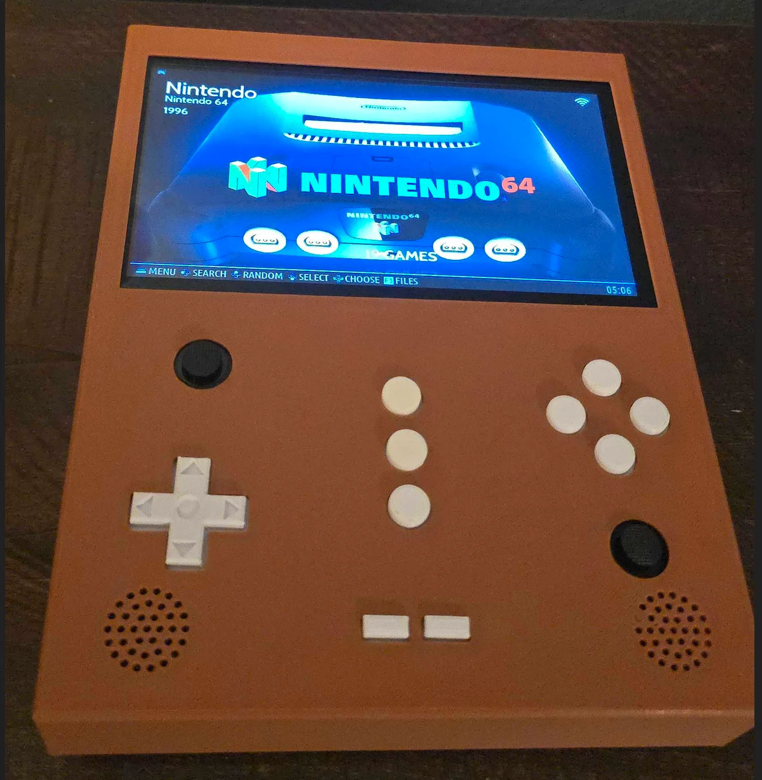
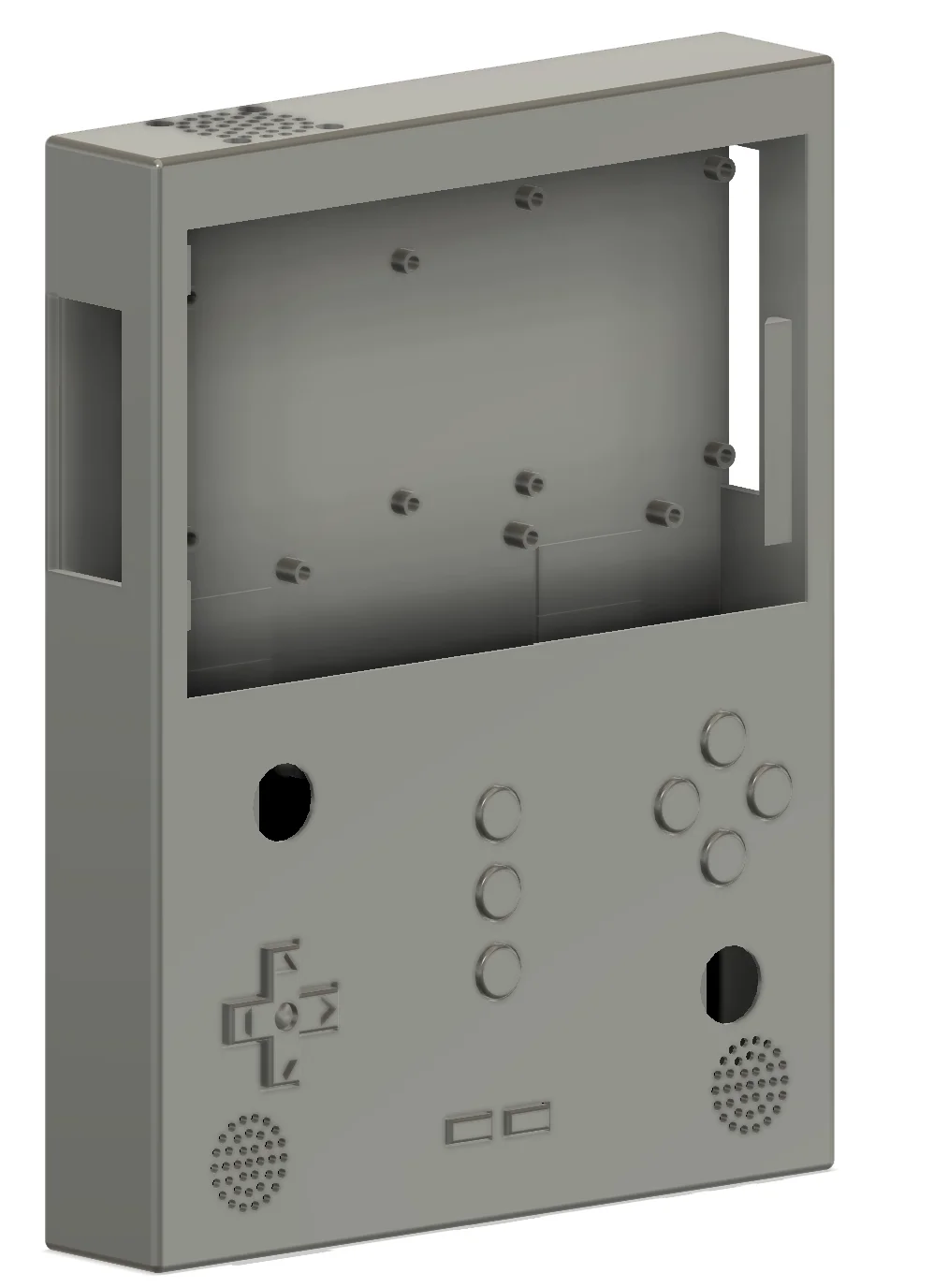
This is a large handheld created using a 7" touchscreen, a raspberry pi, a battery, perfboard, and some buttons. It is an original design.
Raspberry Pi (3,4,5 recommended) + SD Card
1x Apple USB 3.5mm Adapter (For RPi 5 only)
1x 3.5mm stereo cable that can be cut up
Drill + 3mm drill bit
Soldering iron, solder
Electrical Tape
Multimeter
Basic electronic skills
7x Circular Buttons
2x Start/Select Buttons
1x D-Pad
2x Triggers
2x Bumpers
1x Front Shell
1x Rear Cover
Take perfboard and line it up with the holes to identify where you need to drill 3mm holes for mounting and where buttons need to be soldered on. Mark your locations, I used a small knife to scratch the PCB to know where to drill and solder buttons.
Once the buttons are soldered to the perfboard connect one leg of all of the buttons together. This will go to ground. The other end will go to GPIO on either the Arduino or the RPi.
The screws for the perfboard may need to be adjusted to loosen/tighten it for optimal functionality.
The case is designed so that the display can be mounted with no screws or tools. There is a recess on the front of the case for it to fit into and the side of the case can be manually deformed during installation. Please be careful and do not put too much pressure on the screen during installation.
The RPi mounts are a very tight fit with 3mm screws. I had to drill out the mounts on the PiSugar to get 3mm screws to fit it.
The Arduino Nano connects to the RPi over I2C. This Repo contains a user-mode Linux application that will read from GPIO and create a virtual keyboard/joystick using uinput. There are default mappings provided for Batocera and RaspberryPi OS as well as build instructions (Batocera lacks a build toolchain so it must be built on RPi OS and copied over).
Wire A4/A5 (SDA/SCL) on the Arduino to GPIO 2/3 (SDA/SCL) on the Raspberry Pi
You can find the Arduino sketch here.
What this Arduino sketch does is report all of the digital and analog sensors out over I2C for a remote application to query and pull. It attempts to provide battery level information to a 1S battery hooked up to A7 but this is optional to configure. You can find information on setting up the battery in the GitHub repo
It can be flashed like any normal Arduino sketch, there are many guides for this online that can be referenced.
I have created an application to run on the Raspberry Pi that captures the I2C and GPIO lines and presents them as a virtual joystick/keyboard that can be remapped. This is all in the GitHub repo. I recommend starting it as a systemd or Batocera service depending on the platform being used, it must be ran as root.
Please see the github repo for more info on the RPi application
The GPIO buttons can be wired to any GPIO pin on the RPi or digital pin on the Arduino that is not otherwise in use (d2/d3, a4/a5, gpio2/3).
The PSP analog sticks have four pads: VCC, Gnd, UpDown and LeftRight.
UpDown and LeftRight are potentiometer that vary with the position of the stick. Wire VCC and Ground together on both and connect to the power rail, wire UpDown and LeftRight from both sticks to A1, A2, A3, and A6 on the Arduino Nano.
The PiSugar is intended to be mounted on the bottom of the RPi, however we will not be doing this. Instead we will be mounting it next to the RPi and running 5v from the header on it to the RPi, arduino, screen, and amplifier.
Additionally the power button can be connected. This differs per RPi model and is not covered here.
All of the devices (screen, amplifier, RPi, Arduino) should be powered in a star topology from the PiSugar and not routed through the Raspberry Pi (this includes ground).
The amplifier wiring is straightforward. Take a 3.5mm cable that you can cut, identify which wires are Left, Right, and Ground, and solder them to the amplifier board. Solder the output to the speakers to the other pads. I have added extension wires to my speakers to make the wires longer so the front and rear halves of the shell are still separable.
There are no mounts for the amplifier, I just have it taped to an empty spot at the bottom of the back panel
The RPi 5 does not have analog audio out. For my project I have gone with an Apple 3.5mm USB audio adapter because of it's size. If you are using an RPi 5 and wish to use the USB-C port it must be enabled in the config.txt by adding dtoverlay=dwc2,dr_mode=host under [all]
The RPi 5 draws a lot of power. The PiSugar will not power it under heavy load with the amplifier turned up to 100% and it will not handle overclocking the RPi 5. Other RPi generations should not have this issue but I have not tested.
The fan is mostly intended for the RPi 5. I would not run without a heatsink but the fan should be optional for other models. Feel free to add it for any model however.
I had to extend the cables on the Canakit fan I linked because they were very short.
Bylarp3dLikes0Downloads1.4K

 ByjoranLikes0Downloads216

 ByckthLikes148Downloads2.4K

 ByJac2307_889487Likes36Downloads259

 By3dwakeLikes0Downloads363

 ByUpcrid3D_1585693Likes48Downloads214

 ByvladtheinhalerLikes64Downloads257

 BylclabLikes0Downloads293

 BynasikLikes0Downloads277


 ByJaronLikes310Downloads1K

 ByprogoonLikes0Downloads267