



Nema 17 Cycloidal Gearbox
 Byadvanced-hobby-labLikes0Downloads283
Build another version of this model.
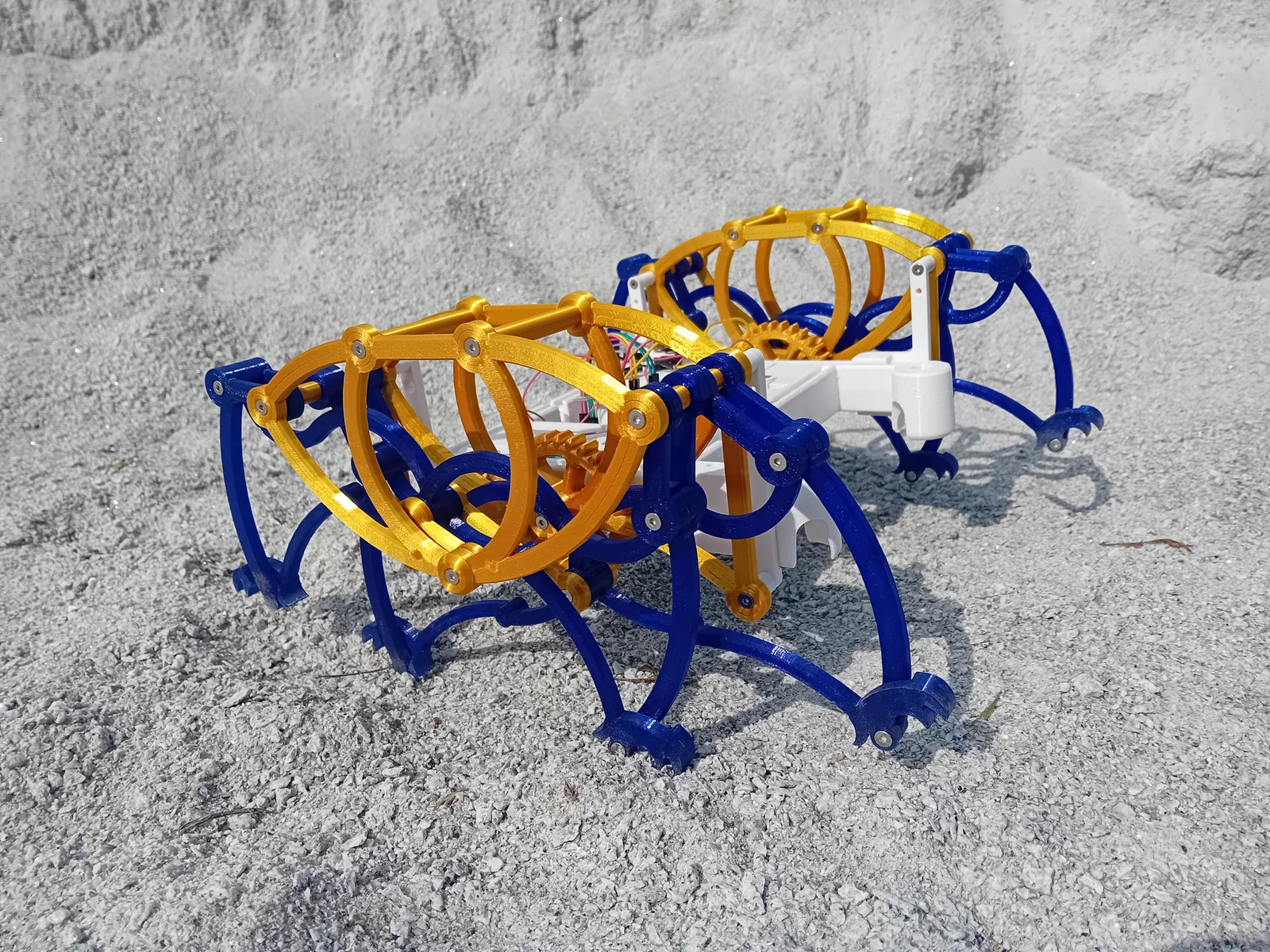
This model is a set of printable legs for a XRP robot. The walking motion is fully mechanical and is driven by the XRP kit motors. The legs are able to walk over obstacles and the robot is also capable of turning.
No extra motor or electronics are required, only printed parts and M3 screws. Assembly is straight forward with an illustrated manual, no gluing involved.
The legs are based on the Strider Linkage mechanism described on the excellent DIY Walkers website: https://www.diywalkers.com/strider-linkage-plans.html . This model brings a few innovations, the main one being a S shaped b2-b5 bar, allowing for a more compact design.
One leg element comes in two variants: b4_with_claws and b4_no_toes. The claw variant is better for hard surfaces, and the no toes version is better for grass. User either of those, but not a combination of them.
The gears have two variants as well: The XRP should use the high torque variant, those using DC motors with 1:90 bi-metal reduction can use either.
I plan to do a remix of this model with a middle chassis more aesthetically alike the legs in the future, with better motors and more flexibility regarding the CPU and motor drivers. If you are interested, leave a like on this model and follow me ;)
Printing should be focused on keeping the robot light. I recommend:
Both PLA and PETG have been tested and work well. ASA/ABS should be even better. It is recommended to print a few pieces first to test for tolerances. The 8mm rods should turn smoothly in the 8mm holes, and the M3 screws should hold well in their holes.
To make the assembly easy, I created a step by step assembly manual with pictures. Other than printed elements, you will need M3x10mm screws with conic heads and M3 threaded rods. More details in the assembly manual.
Due to availability issues, I was unable to get a XRP kit. But great care was taken to test this model with elements compatible and comparable to what is in the XRP kit. When possible, measurements were taken from the datasheet rather than from the hardware I use. If still there is any compatibility issue, I will provide a fix ASAP.
The prototype used the following electronic parts:
All source files are available on onshape.com, with possibility to export in various formats. Link in the assembly manual.
Byadvanced-hobby-labLikes0Downloads283

 ByWolf_115355Likes513Downloads8.4K

 ByZED4EverLikes313Downloads5.2K

 ByfifindrLikes500Downloads4K

 ByVC_DesignLikes679Downloads3.6K

 ByDan Schwartz SchwartzLikes744Downloads3.4K

 ByKNIN_CustomLikes112Downloads433

 ByUpcrid3D_1585693Likes808Downloads2.1K

 ByWilko_SLOLikes935Downloads2K

 Bychubbs8697_2027893Likes585Downloads1.7K

 Byquibeck_3353173Likes965Downloads1.9K

 BySeppoTakaloLikes960Downloads1.9K