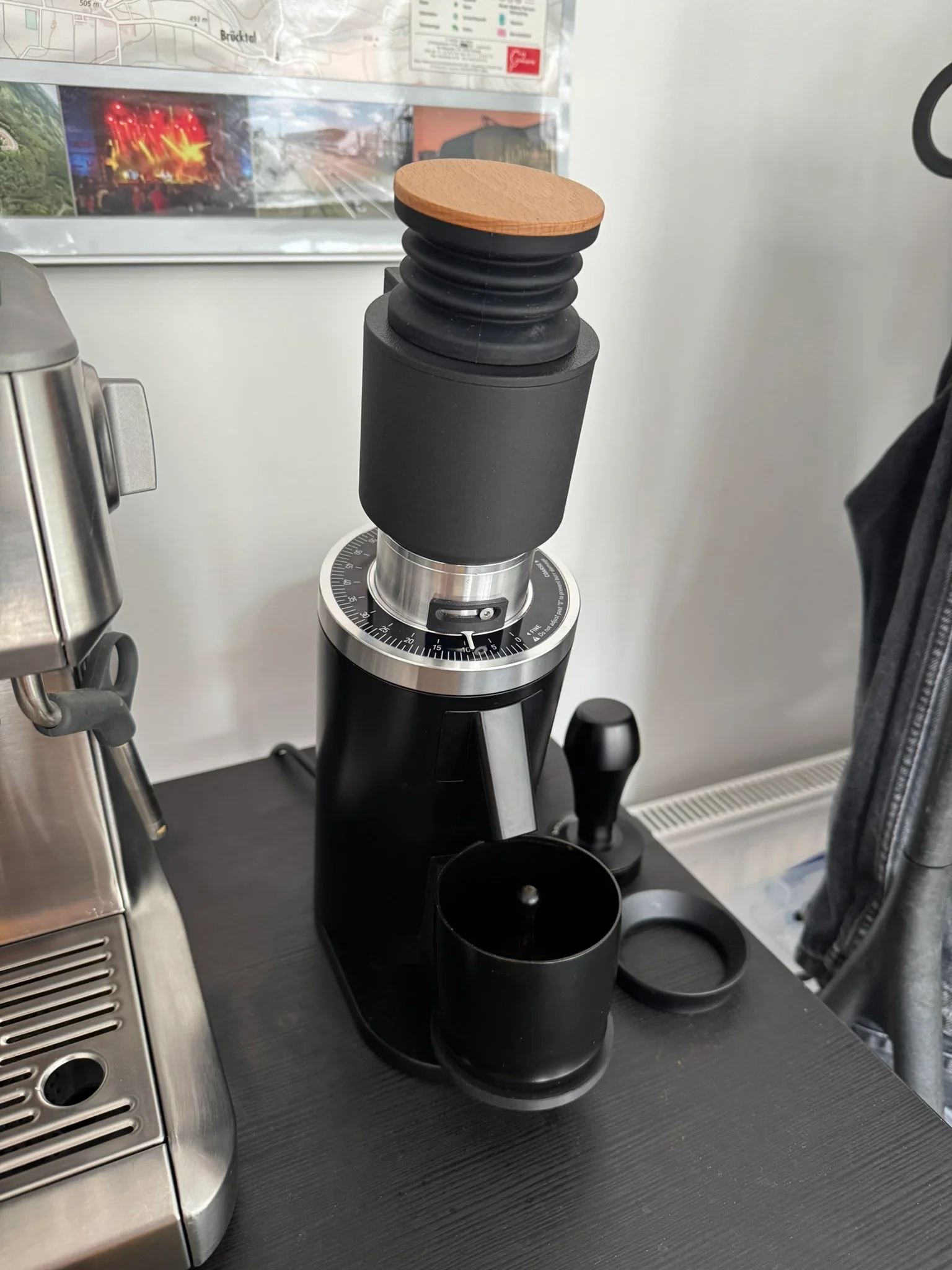

F3D
Bộ cấp liệu chậm DF64/DF54 11 / 13

13 images

Đồ Gia Dụng

Bộ cấp liệu chậm DF64/DF54

By LeeTaylor_1593949

Downloads
102
Likes
24
Views
1,371
Remixes
2

Files 8 14.8 MB

  • Cap_1766643872.stlSTL · 245.6 KB
  • Feeder_Disk_1766643873.stlSTL · 999.4 KB
  • Bellows_Ring_1766643874.stlSTL · 139.6 KB
  • Motor_Clamp_1766643875.stlSTL · 336 KB

Make a variant with AI

Build another version of this model.

Open Studio

Remix versions 2

See all 2 remixes

Description

Sometimes the feeder disk can jam, and sometimes it struggles to pick up the last bean. I've included the STEP files in case people want to make their own adjustments; please comment if you find a perfect solution!

Edit 01/09/25: hopper internal fillet extended to steepen the feed surface into the disk.

Hardware/Parts List

  1. Standard open 2 x AAA battery holder
  2. 5 x M2*6mm machine screws
  3. 5 x M2 heat set inserts (optional but recommended)
  4. Mini on/off push button switch (Adafruit LG-15F) 
  5. N20 micro metal gearmotor 298:1
  6. Male/female PH2.0 connectors (or other similar size)

Tools List

  1. Screwdriver
  2. Soldering iron

Build Instructions

  1. Print all components in folder (no supports required)
  2. Insert heat set inserts to the Hopper as shown (if you don't want to use heat set inserts, print the hopper with integrated threads)
  3. Solder the push button across one of the battery pack outputs so that it creates open/closed circuit, aim for short wire from battery pack to switch so it can sit neatly on top
  4. Solder PH2.0 connectors (or whatever else you want to use) to the battery pack and motor, making sure polarisation results in correct rotation direction (anti-clockwise when looking at end of shaft)
  5. Feed the battery pack into its slot, with the connector coming through the hole at the bottom (may require pliers/tweezers)
  6. Feed motor through the hole into its position, followed by the Motor Clamp. Ensure that the clamp's small flange is at the rear of the motor, this prevents it from sliding out the back. Secure the clamp with the screws, here is where you can adjust the exact angle of the shaft while you tighten to ensure it's perpendicular to the internal hopper face.
  7. Plug the motor into the battery pack and test it works with the switch
  8. Secure the Lower Cover with the screws to cover the internals
  9. If you use the bellows, attach the Cap and Bellows Ring components with a press fit (or CA glue if necessary)
  10. Attach the Feeder Disk to the motor shaft with a press fit
  11. Attach the button to the Cap through its hole with a press fit
  12. Secure the cap onto the hopper with a press fit
  13. Attach to the grinder funnel with a press fit (can be quite tight depending on the printer setup)

Read more Show less

Print spec

Formats
stepstl
Model files
8
Total size
14.8 MB
Largest file
8.4 MB

0 comments

See all