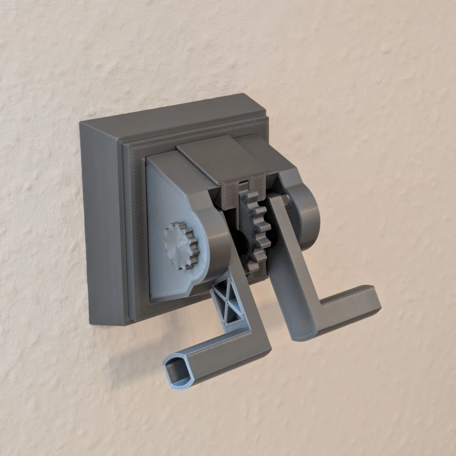
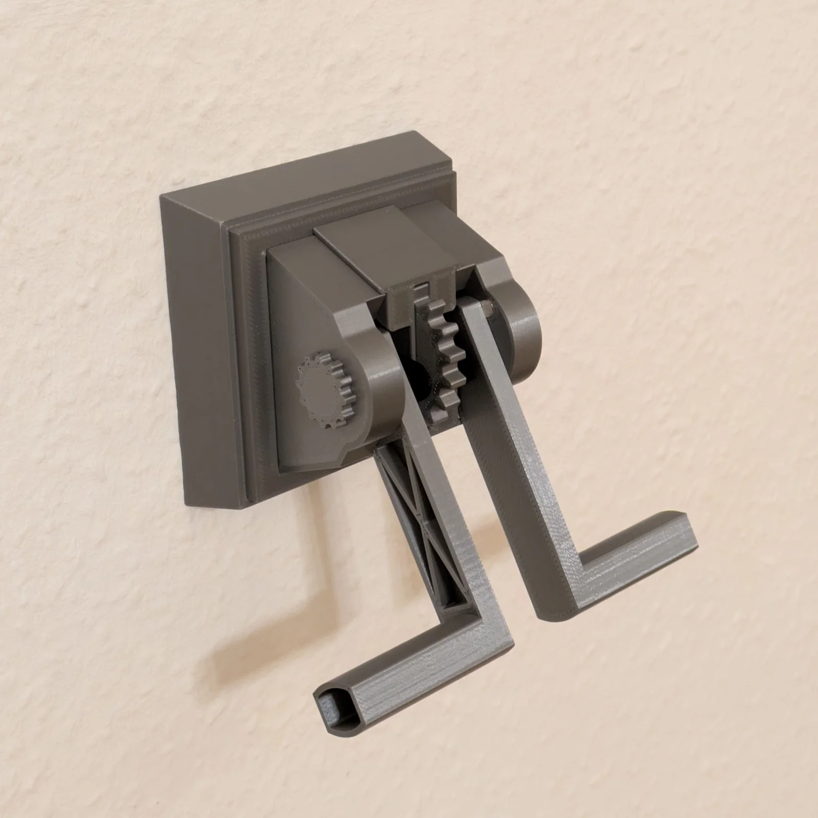
The old, standard-issue rocker switch looked a little underwhelming for its duty of providing power to my heavy-duty 3kW BBQ grill. So, I upgraded it with a nice steampunk-style lever switch.
The lever assembly fits the Busch-Jaeger 2XXX series flush-mounting dual switch (verified on 2400/5 US and 2000 U, but it should fit others as well).
Update 2025-10-29: Added shorter lever variant.
--------
DISCLAIMER: Use this object at your own risk! I will assume no liability for any injury or property damage that results from the print, assembly or use of this object.
--------
Material
Filament: Use any material you like. I recommend PETG for the rockers.
Needed to complete:
- 6 round magnets, 5 mm diameter, 2 mm thickness
- Some glue (possibly)
Printing: The print shouldn't be a big challenge. Refer to the example 3mf project for parts orientation and support settings.
Parts you'll need to print:
- 1x Frame
- 1x Frame Cover
- 2x Rocker
- 1x Lever Bearing Mount 1
- 1x Lever Bearing Mount 2
- 2x Lever
- 2x Axle Plug
- 2x Guide Pin
- 1x Center Cover
- 1x Cogwheel
Assembly
Preparing the levers
- Push one of the magnets into the hole on the side of the Lever (not into the axle!). The magnet should press-fit into the hole; if not, apply some glue.
- Snap another magnet onto the one you just inserted in the Lever. Insert the Lever axle into the Bearing Mount. Rotate the Lever into one of the end positions so that the magnet aligns with the hole on the Bearing Mount and push it all the way in. Again, if it doesn't stay in place, apply some glue, but make sure the glue fully cures before inserting the Lever again.
Repeat this procedure for the other end position.
- With the Lever inserted in the bearing and held in place by one of the magnets, Insert the Axle Plug into the lever axle to secure it. Apply some glue if necessary, but be careful not to get any glue into the bearing!
- Insert a Guide Pin into the back side of the Lever. Apply some glue if necessary.
- Repeat all of this for the other lever.
Assembling the switch on the wall
- Push one of the Rocker parts in each of the switch rockers. Make sure the hole on the rocker parts faces outward. The parts should press-fit into the chassis; if not, just scale the part accordingly on the XY plane and re-print.
- Place the Frame on the flush-mounting switch. Make sure it is centered and hold it in place.
- Insert the Frame Cover into the Frame. The two small feet on the Cover need to be on the upper side; make sure they go into the corresponding holes in the base plate.
- Take one of the Bearing Mount / Lever assemblies and insert it into the frame. This time, the small foot needs to be facing down; again make sure that it goes into the corresponding hole on the base plate.
You'll need to push the Rocker aside a little bit to slide the pin into the hole on the Rocker.
Once this step is done, the assembly should already be able to hold itself in place.
- Repeat the step 4 for the other Bearing Mount / Lever assembly.
- Take the Center Cover and check the small latches on its underside. They have different sizes which need to align with the corresponding voids on the frame; it won't fit if it's placed the wrong way. The small gap should be facing downwards. Slide the Center Cover over the levers and into the frame. Insert the upper side first, then latch the lower side into place.
The entire assembly should now sit firmly in place.
- Insert the decorative Cogwheel into the corresponding hole on the Center Cover.
(Feel free to print something else to use in its place - it's just for the looks. Just make sure it doesn't get in the way of the levers or rockers.)
Again, apply some glue if necessary.
…aaand you're done! Verify that the switch still works as intended, and enjoy the klicky-klacky levers when turning your power on and off!




 BybobmakesLikes2.5KDownloads17.5K

 By178222178222_2484344Likes449Downloads1.7K

 Byquibeck_3353173Likes1.5KDownloads11.5K

 ByVaclav_ZahradkaLikes181Downloads1.2K

 ByowlartLikes527Downloads1.3K

 Bytjfenwick_306961Likes385Downloads1K

 ByAWSWLikes148Downloads581

 ByfifindrLikes216Downloads605

 Bym-collectableLikes0Downloads3.9K

 Byskloter_271869Likes147Downloads427

 Byelectric_pierogiLikes37Downloads386

 ByTommy3DLab_2023125Likes636Downloads2.5K