


Còi Tàu Hơi Nước Mini
 ByfifindrLikes500Downloads4K
Build another version of this model.
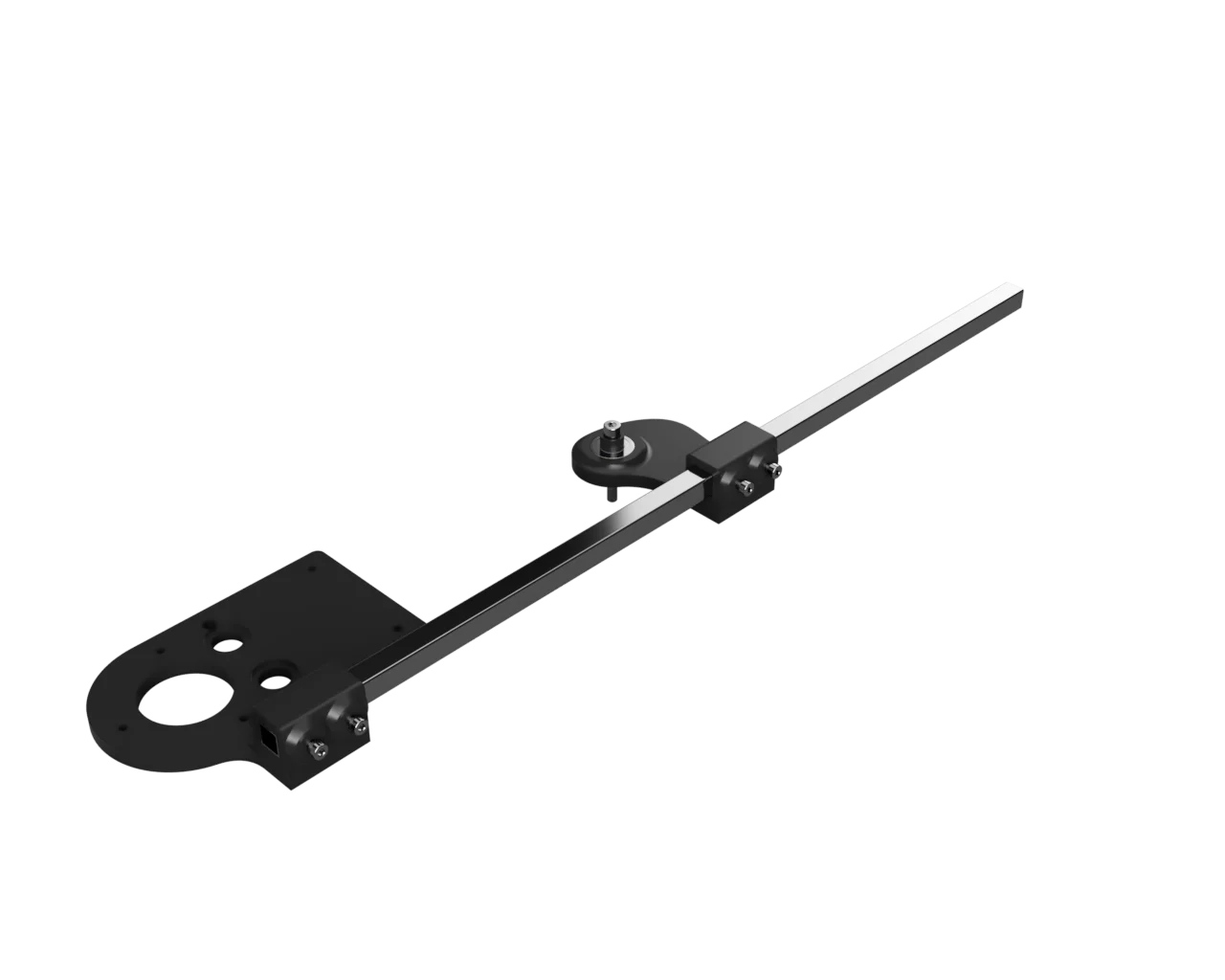
This model is a circle router to be used with a Bosh GKF 12V-8. It uses a 12x12 mm extrusion for the arm. The minimum routing diameter is 240 mm and the maximum depends on the 12x12 mm extrusion length you use.
This model is based on my other model Base Plate for Bosh GKF 12V-8. The parametric model is provided for the GKF 12V-8 so feel free to use it for your customer design.
Name
Qty
The main design of the base plate can be downloaded here: Base Plate for Bosh GKF 12V-8.
1
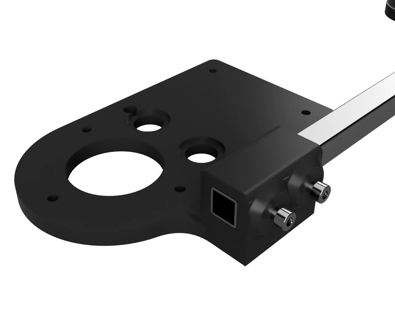
The center plate is fitting a 608 bearing as center point.
1
The insert is design to connect with a 12x12 square extrusion. There are 2 M4 nuts and screws per insert to secure the 12x12 extrusion. Each insert is attached to the respective plate with 2 M3 threaded inserts and screws.
2
The pivot is design to fit a 5 mm screw. You can easily design your own pivot as soon as it fit the inside diameter of a 608 bearing (⌀8 x 7 mm).
1
Name
Qty
Minimum length should be 160mm for a 240mm routing diameter. You need 40 mm more than the max routing radius needed.
1
Standard M4 hexagonal nut, should have 7 mm hexagonal size.
4
Any M4x10 screw will work, head type as available.
4
Use 3D printing M3 threaded insert, length 5.7 mm and 4.6 mm external diameter.
4
Recommend to use hexagonal socket head M3x10 screw. In any case the head should fit in the Ø6x3mm counterbore.
4
Recommend using 608ZZ bearing (sealed).
1
Any screw or shaft you would like to use as center point. If different than Ø5 mm, you need to design your own pivot.
1
Print with the routing face against the built plate. I recommend printing with .20mm layer height and 25% grid infill, 3 perimeters and 5 bottom layers. I recommend enabling the feature extra perimeters on overhang for a better result on the counterbores.
Print with the routing face against the built plate. I recommend printing with .20mm layer height and 25% grid infill, 3 perimeters and 5 bottom layers.
Print with the end face against the build plate. I recommend printing with .20mm layer height and 25% grid infill, 3 perimeters.
Print with the larger end face against the build plate. I recommend printing with .20mm layer height.
Prepare the x2 Dovetail Inserts by setting the x2 Threaded Inserts each.
Set the 2x M4 Nuts each.
Secure the Nuts by sliding in the 12x12mm tube.
Set the Base Plate with the first Dovetail Insert and using two M3x10 screws.
Set the Center plate with the second Dovetail Insert and using two M3x10 screws.
Set the 608 Bearing in the center position.
Set the Pivot and the Ø5 Screw or any Ø5 shaft.
ByfifindrLikes500Downloads4K

 ByVC_DesignLikes679Downloads3.6K

 ByDan Schwartz SchwartzLikes744Downloads3.4K

 Bychubbs8697_2027893Likes585Downloads1.7K

 Byquibeck_3353173Likes965Downloads1.9K

 ByRungeKuttaLikes229Downloads1.2K

 ByEadubsLikes228Downloads1.3K

 ByJeremyVillalo_760366Likes68Downloads767

 ByZED4EverLikes313Downloads5.2K

 Bykjus_448782Likes314Downloads673

 BySchmitzBertLikes95Downloads629

 ByNathanKun_342409Likes132Downloads590